Transmission equipment for communication

A transmission equipment and communication technology, which is applied in the directions of antennas, foldable antennas, and retractable units suitable for movable objects, and can solve the problems of limited detection range, bulky antennas, and inability to detect high-elevation sky waves. The effect of improving dynamic range and reducing antenna noise

Inactive Publication Date: 2018-02-16
成都美数科技有限公司
View PDF3 Cites 0 Cited by
  • Summary
  • Abstract
  • Description
  • Claims
  • Application Information

AI Technical Summary

Problems solved by technology

[0003] The technical problem to be solved by the present invention is the design principle of passive antenna. The designed antenna needs to achieve omnidirectional reception, and the volume of the antenna will be very large. The antenna designed by adopting the design principle of active antenna mostly adopts a single polarization antenna, which cannot Detecting high-elevation sky waves, the detection range is greatly limited. The purpose is to provide a transmission device for communication and solve the design principle of passive antennas. The designed antenna must achieve omnidirectional reception, and the antenna volume will be very large. , Antennas designed using active antenna design principles mostly use single-polarization antennas, which cannot detect sky waves at high elevation angles, and the detection range is greatly limited

Method used


Image

  • Transmission equipment for communication
  • Transmission equipment for communication

Examples


Embodiment 1

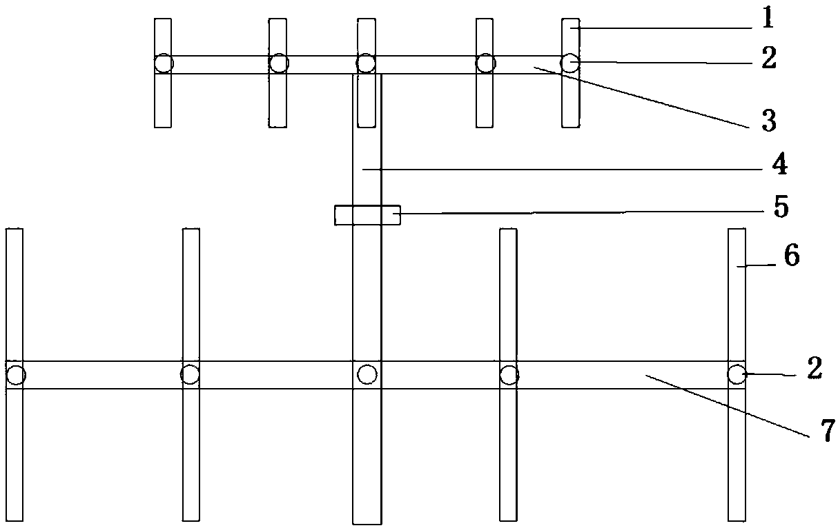
[0021] Such as Figure 1-2 As shown, a transmission device for communication of the present invention includes a short antenna 1, the number of which is an odd number, and is sequentially connected to a short telescopic rod 3, and the short antenna 3 in the middle position is connected to one end of the antenna 4 Spring connection, the other end of the connecting antenna 4 is connected to the long telescopic rod 7 through the spring block 2, the connecting antenna 4 is the midpoint, and the two sides of the long telescopic rod 7 are connected to the long antenna 6 in turn, and the number of the long antenna 6 is more than The number of short antennas 1 is less than 1; all the short antennas 1 and long antennas 7 connected to the long telescopic rod 7 and the short telescopic rod 3 are connected by spring blocks.

[0022] When working: it can detect sky waves, ground waves and high elevation sky waves, etc., which greatly improves the detection range of the antenna.

Embodiment 2

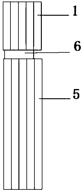
[0024] Such as Figure 1-2 As shown, a transmission device for communication of the present invention includes a short antenna 1, the number of which is an odd number, and is sequentially connected to a short telescopic rod 3, and the short antenna 3 in the middle position is connected to one end of the antenna 4 Spring connection, the other end of the connecting antenna 4 is connected to the long telescopic rod 7 through the spring block 2, the connecting antenna 4 is the midpoint, and the two sides of the long telescopic rod 7 are connected to the long antenna 6 in turn, and the number of the long antenna 6 is more than The number of short antennas 1 is less than 1; all the short antennas 1 and long antennas 7 connected to the long telescopic rod 7 and the short telescopic rod 3 are connected by spring blocks. The number of short antennas 1 is five, and the number of long antennas 6 is four. The connecting antenna 4 is provided with a limit block 5, and the limit block 5 is...


PUM


Abstract

The invention discloses transmission equipment for communication. The transmission equipment comprises an odd number of short antennas which are connected in sequence to a short telescopic rod, the short antenna in the middle is connected with a spring at one end of a connecting antenna, the other end of the connecting antenna is connected with a long telescopic rod through a spring block, the connecting antenna is a midpoint, long antennas are connected in sequence to two sides of the long telescopic rod, and the number of the long antennas is one less than that of the short antennas; and allthe short and long antennas connected to the long telescopic rod and the short telescopic rod are connected by spring blocks. The number of the short antennas is 5, and the number of the long antennas is 4. The connecting antenna is provided with a limiting block, and the limiting block is located above the highest point of the long antennas and below the lowest point of the short antennas. The length of the limiting block is smaller than the total width of all the short antennas. The short antennas are as wide as the long antennas.

Description

technical field [0001] The invention relates to an antenna, in particular to a transmission device for communication. Background technique [0002] The development of radio technology is closely related to the development of antenna technology. Today's receiving antenna design generally adopts two methods: active and passive. In the design of a passive antenna, the ratio of the maximum received power to the power density is usually used to determine the effective aperture of the antenna, namely: A=Pmax / S. In the formula, A is the effective aperture of the antenna; Pmax is the maximum power received; S is the power density. In the design of the active antenna, the gain of the active network is used to compensate the decrease in the gain of the passive antenna due to the smaller size, so as to achieve the purpose of improving the radiation efficiency of the antenna. The design principle of the passive antenna, the antenna designed to achieve omnidirectional reception, the a...

Claims


Application Information

Patent Timeline
Patent Type & Authority Applications(China)
IPC IPC(8): H01Q21/00H01Q1/10H01Q1/32
CPCH01Q1/10H01Q1/32H01Q21/00
Inventor 矣峻岭杜江
Owner 成都美数科技有限公司
Why Eureka
Try Eureka