USB end for computer

A computer and terminal technology, applied in computing, computer peripheral equipment connectors, coupling devices, etc., can solve problems such as collisions

Inactive Publication Date: 2018-02-16
重庆优之唯电子科技有限公司
0 Cites 1 Cited by

AI-Extracted Technical Summary

Problems solved by technology

[0002] In the daily use of the computer, it is often necessary to insert and connect peripherals through the USB port, such as U disk, wireless disk, etc. In order to facilitate plugging and unplugging, the exis...

Method used

During implementation, the backing plate can be provided with the backing plate on the opposite side of the golden finger, and the strength can be improved, and an elastic pad can be established between the online board and the backing plate, so that the terminal contact passes through the elastic variable; the prismatic housing has five or six faces It is better; a dial can be connected to the rotating shaft for turning and rotating without touching the USB peripherals; a limit block is connected to the rotating shaft against the bracket to limit the rotation angle and prevent the vortex-shaped PCB cable from transitioning around twist.
Embodiment of the present invention is shown in Fig. 1, 2, and this computer USB end is provided with rotating body and USB end, and rotating body is provided with two relative prismatic shells 1, and present embodiment prismatic shell is Six sides, during implementation, you can choose between three and ten sides according to the number of ports required. The outer end of the prismatic shell is provided with an end shell 2, and the end shell is connected with a prismatic connector 3 extending outward. The sides of the connector are connected to the prism The sides of the housing are one-to-one corresponding and parallel, and the edges of the connecting body are rounded. Lin...

Abstract

The invention discloses a USB end for a computer. The USB end is characterized by comprising connectors, wherein various side surfaces of each connector correspond to various side surface of one prismatic shell one by one and are parallel to various side surfaces of the prismatic shell; an outer end of each connector is connected with one rotating shaft; each rotating shaft is connected with one bracket; a vortex-shaped PCB cable is arranged on an outer segment of each connector; gold fingers connected with a mainboard are arranged at the outer end of each PCB cable; each PCB cable is providedwith an inner ring laminated with the outer surface of the corresponding connector; each inner ring is connected to line boards which extend to an inner segment of the corresponding connector at thecenter positions of various surfaces of the connector; each line board is provided with one corresponding gold finger; slots for accommodating the edges of corresponding line boards are formed in eachconnector at two sides of the line boards; via holes are formed in each end plate corresponding to the line boards; sockets are arranged in the front sides of USB end bodies and are exposed from openings in the side surfaces of the prismatic shells; the back sides of the USB end bodies are connected with bottom plates which extend towards two sides; and terminals connected with the sockets are arranged on the bottom surfaces of the corresponding bottom plates. The space in a case can be fully utilized, occupation on a panel is reduced and multi-position connection is achieved.

Application Domain

Digital data processing detailsCoupling contact members +2

Technology Topic

Surface fittingComputer case +5

Image

  • USB end for computer
  • USB end for computer

Examples

  • Experimental program(1)

Example Embodiment

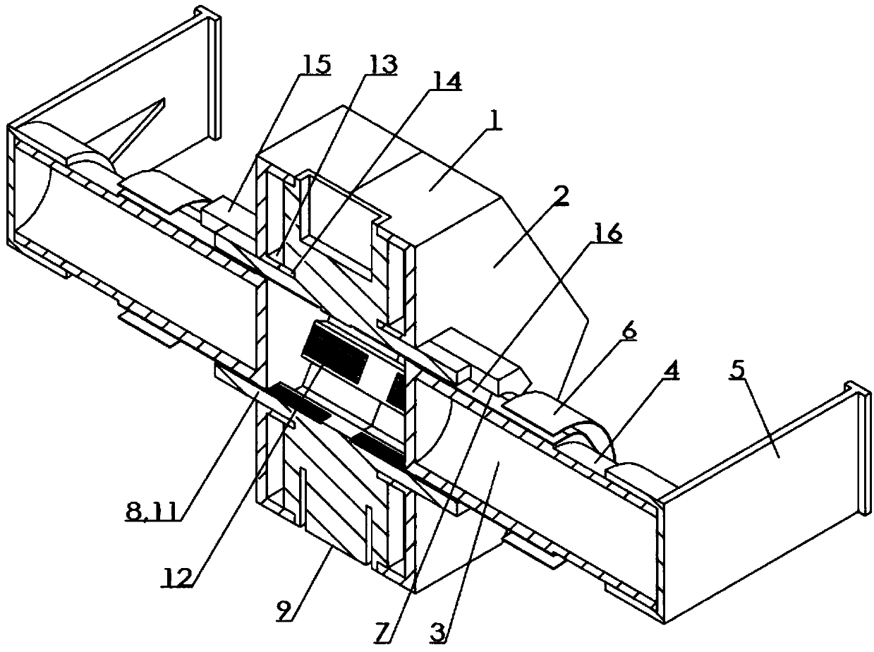
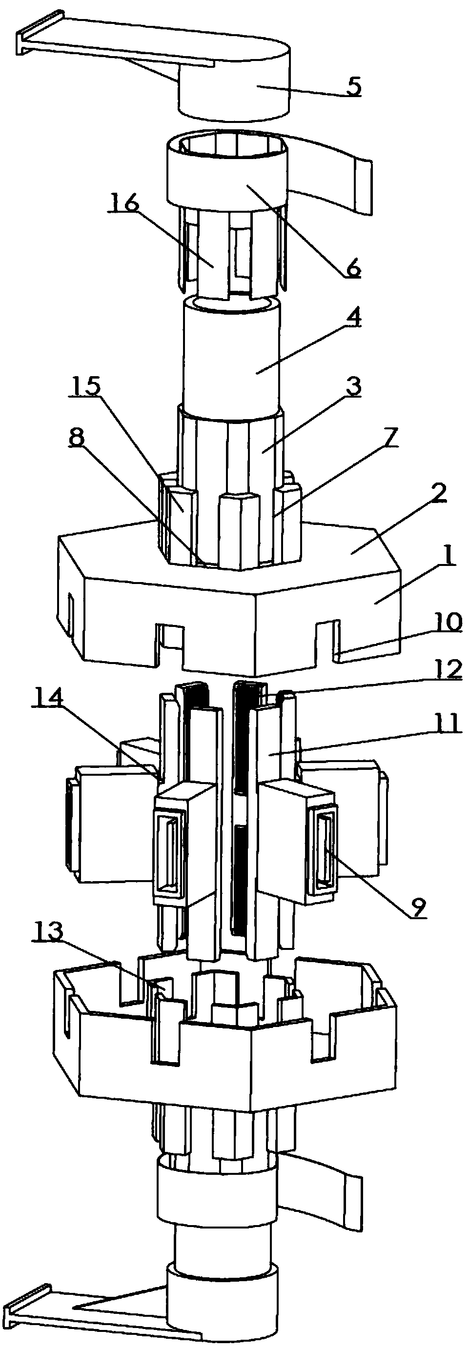
[0014] Examples of the present invention figure 1 , 2 As shown, the computer USB terminal is provided with a rotating body and a USB terminal, and the rotating body is provided with two opposite prismatic shells 1. The prismatic shell of this embodiment has six sides, and the number of ports can be determined according to the needs during implementation. Choose between three to ten sides, the outer end of the prismatic shell is provided with an end shell 2, and the end shell is connected with a prismatic connecting body 3 extending outward, and each side of the connecting body corresponds to and is parallel to each side of the prismatic shell, There are rounded corners at the edge of the connecting body, the connecting body end is connected with a rotating shaft 4, and the rotating shaft is connected with a bracket 5, which is used to connect with the chassis. The gold finger connected to the main board, the PCB cable is provided with an inner ring that fits on the surface of the connecting body, and the inner ring is connected to the inner ring at the center of each surface of the connecting body. , the connecting body on both sides of each line board is provided with a slot 7 for accommodating the edge of the line board, and the corresponding line board is provided with a via hole 8 on the end plate. It has a socket 9, which is exposed from the opening 10 on the side of the prismatic housing. The back of the USB terminal is connected to a bottom plate 11 extending to both sides. The bottom surface of the bottom plate is provided with a terminal 12 connected to the socket. The gold fingers on the board are in contact with each other to realize electrical connection, and the USB terminal is positioned through the rib 13 on the end plate and its own card slot 14; there are plug-in boards 15 on both sides of the via hole to form a groove that matches the bottom plate, and the positioning is better .
[0015] When the present invention is in use, it is installed inside the case, and an opening is set on the panel, and a USB peripheral is inserted into the forward socket, and then the peripheral can be screwed into the case, so that it will not protrude from the panel, and will not affect work due to daily contact. Especially the long-term plug-in peripherals, such as wifi disk, can make full use of the internal space of the chassis, save the panel occupation, and realize multi-bit connections.
[0016] During implementation, a backing plate can be provided on the opposite side of the gold finger to improve the strength, and an elastic pad can be provided between the wiring board and the backing plate to pass elastic variables for the terminal contact; the prismatic shell has five or six surfaces is better ;A thumb wheel can be connected to the rotating shaft for turning and rotating without touching the USB peripherals; the rotating shaft is connected with a limit block that resists the bracket to limit the rotation angle and prevent the vortex-shaped PCB cable from being twisted.
[0017] In summary, the above is only a preferred embodiment of the present invention, and all equivalent modifications and additions made in accordance with the present application are regarded as the technical scope of the present invention.

PUM

no PUM

Description & Claims & Application Information

We can also present the details of the Description, Claims and Application information to help users get a comprehensive understanding of the technical details of the patent, such as background art, summary of invention, brief description of drawings, description of embodiments, and other original content. On the other hand, users can also determine the specific scope of protection of the technology through the list of claims; as well as understand the changes in the life cycle of the technology with the presentation of the patent timeline. Login to view more.
Why Eureka
Try Eureka