Treating fluid pressurizing tank used for digital garment printing machine

A technology for treating liquid and printing machine, applied in the field of pressurized tanks, can solve the problems of lag closing of the device for spraying the treatment liquid, affecting the life of the pump, and decreasing the concentration of the treatment liquid, etc., so as to improve the stability and uniformity, and improve the printing effect. , the effect of long service life

Inactive Publication Date: 2018-02-23
广东世纪方达数码科技有限公司
View PDF0 Cites 0 Cited by
  • Summary
  • Abstract
  • Description
  • Claims
  • Application Information

AI Technical Summary

Problems solved by technology

[0003] 1. Since the treatment liquid is generally weakly acidic, this will seriously affect the life of the pump;
[0004] 2. When there are air bubbles in the pipeline, the treatment liquid cannot be pumped out of the container normally;
[0005] 3. When the pump is turned on, it takes a short time for the pump to reach the rated speed. Before reaching the rated speed, the treatment liquid is sprayed unevenly; similarly, when the pump is turned off, it takes a short time for the pump to stop, so that It will cause the device for spraying the treatment liquid to close with a lag, and the action of stopping the spraying of the treatment liquid will be delayed, and the nozzle will still spray out the residual treatment liquid, resulting in unstable spraying of the treatment liquid and prone to backflow;
[0006] 4. The pressure of the treatment liquid sprayed by different nozzles is different, resulting in uneven treatment liquid sprayed on the fabric, which affects the printing effect;
[0007] 5. The container containing the treatment liquid cannot be completely sealed, and the acidic components in the treatment liquid will volatilize, thereby reducing the concentration of the treatment liquid

Method used


Image

  • Treating fluid pressurizing tank used for digital garment printing machine

Examples


Embodiment Construction

[0027] In order to further illustrate the technical means and functions adopted by the present invention to achieve the intended purpose, the specific implementation modes of the present invention will be described in detail below in conjunction with the accompanying drawings and preferred embodiments.

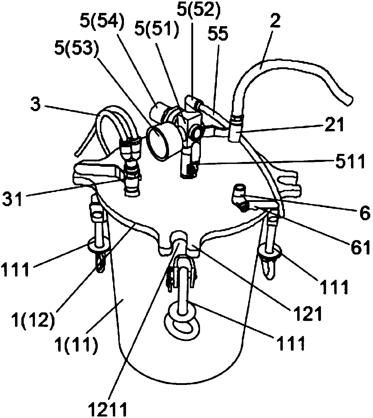
[0028] Please refer to figure 1 , the embodiment of the present invention provides a digital garment printing machine processing liquid pressurized tank, including a tank 1, a liquid inlet pipe 2 and a number of liquid outlet pipes 3 arranged on the tank body 1, and a tank body 1 A liquid introduction pipe that is connected with the liquid outlet pipe 3. At the same time, it also includes an air pressure regulator 5 arranged on the tank body 1, wherein the air pressure regulator 5 includes an air pressure regulating pipe 51 arranged on the tank body 1, a pressurized inlet pipe arranged on the air pressure regulating pipe 51 Gas connector 52, a pressure gauge 53 arranged on th...


PUM


Abstract

The invention discloses a treating fluid pressurizing tank used for a digital garment printing machine. The treating fluid pressurizing tank comprises a tank body, a liquid inlet pipe and a pluralityof liquid outlet pipes which are arranged on the tank body, a liquid guide pipe which is arranged in the tank body and communicates with the liquid outlet pipes, and an air pressure regulator which isarranged on the tank body. The air pressure regulator comprises an air pressure regulating pipeline arranged on the tank body, a pressurizing air inlet connector arranged on the air pressure regulating pipeline, a pressure gage arranged on one side of the air pressure regulating pipeline, and a regulating knob arranged on one side of the air pressure regulating pipeline. An air inlet pipe is connected to the pressurizing air inlet connector. According to the treating fluid pressurizing tank, it can be guaranteed that a treating fluid is pressed out fast at constant positive pressure, the spraying-out stability and uniformity are improved, and the phenomenon of backflow of the treating fluid does not occur; and meanwhile, it is guaranteed that the treating fluid in different spray nozzlescan be sprayed out with the same pressure, accordingly, the treating fluid is uniformly sprayed onto fabric, and the spray printing effect can be improved easily.

Description

technical field [0001] The invention relates to a pressurized tank, in particular to a treatment liquid pressurized tank for a digital garment printing machine. Background technique [0002] At present, when the garment printing machine uses pigment ink for printing, in order to make the color of the ink more delicate and the adhesion of the ink better, it is usually necessary to pre-treat the cloth before printing, that is, spray the treatment liquid. The traditional spraying method is to use a pump to pump the treatment liquid from the storage container, pass through the corresponding pipeline, and finally spray it out from the nozzle. This method has the following disadvantages: [0003] 1. Since the treatment liquid is generally weakly acidic, this will seriously affect the life of the pump; [0004] 2. When there are air bubbles in the pipeline, the treatment liquid cannot be pumped out of the container normally; [0005] 3. When the pump is turned on, it takes a sho...

Claims


Application Information

Patent Timeline
Patent Type & Authority Applications(China)
IPC IPC(8): B41J11/00
CPCB41J11/0015
Inventor 胡建芳向华
Owner 广东世纪方达数码科技有限公司
Why Eureka
Try Eureka