Induction mechanism, motion device and motion system

A technology of induction part and skateboard mechanism, applied in the field of motion system, can solve the problems of high maintenance cost, strong mechanical vibration, parts damage, etc., to reduce mutual interference and inconsistency, accurate and stable motion control, and reduce production and maintenance costs Effect

Inactive Publication Date: 2018-02-23
深圳东风汽车有限公司
View PDF6 Cites 0 Cited by
  • Summary
  • Abstract
  • Description
  • Claims
  • Application Information

AI Technical Summary

Problems solved by technology

However, as we all know, the sensor is easily disturbed, resulting in insufficient control accuracy, which leads to poor coherence between actions, and there is still strong mechanical vibration caused by incoherent action conversion between mechanical structures, which is easy to cause zero Parts are damaged, and later maintenance costs are higher

Method used


Image

  • Induction mechanism, motion device and motion system
  • Induction mechanism, motion device and motion system
  • Induction mechanism, motion device and motion system

Examples


Embodiment 1

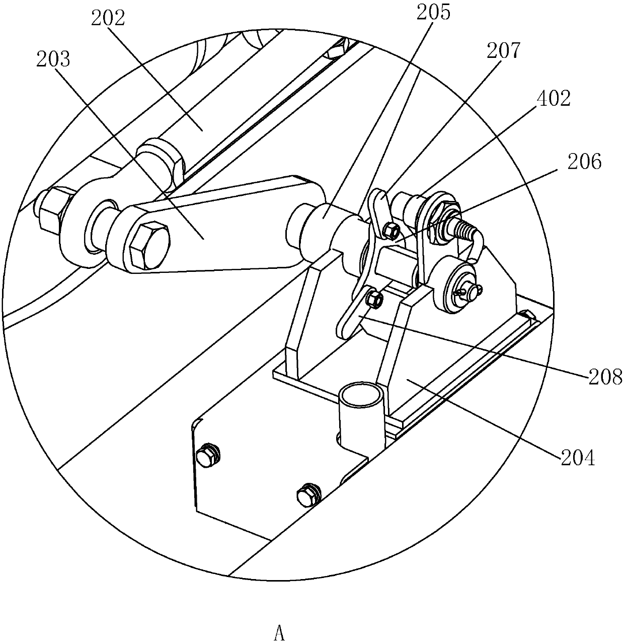
[0040] An induction mechanism, especially a two-position induction mechanism, includes a follower and a first sensor that are connected to an external drive through a connecting piece, the drive moves reciprocatingly, and the follower moves with the drive through the connecting piece. The moving part moves synchronously, the driven part is provided with a sensing part, and the sensing part is provided with a first sensing part and a second sensing part which follow the moving part to move synchronously. When the original moving part moves to two different positions of its reciprocating motion track, The first sensing part and the second sensing part can be sensed by the first sensor respectively.

[0041] When the original moving part reciprocates, the driven part is driven to reciprocate through the transmission of the connecting part, and then the first sensing part and the second sensing part are driven to reciprocate to the sensing end of the first sensor, so that one senso...

Embodiment 2

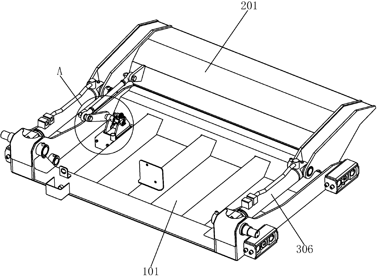
[0050] a movement device such as figure 1 and figure 2 As shown, it includes the scraper mechanism 201 as the driving element, the slider mechanism 101, the power mechanism and the two-position induction mechanism in Embodiment 1, the connecting rod 202 as the connecting piece, the crank 203 as the follower, the scraper mechanism 201 and the The slide mechanism 101 is connected in rotation, and the scraper mechanism 201 is driven by the power mechanism to perform reciprocating opening and scraping movements.

[0051] By using the double-position sensing mechanism in Embodiment 1, it is possible to realize the position sensing of the opening and scraping motion states of the scraper mechanism 201, thereby reducing the number of sensors used, reducing production costs, and making the scraper mechanism 201 The position sensing of the motion state is more accurate and stable, which makes the switching between opening and closing of the scraper mechanism 201 more consistent.

[...

Embodiment 3

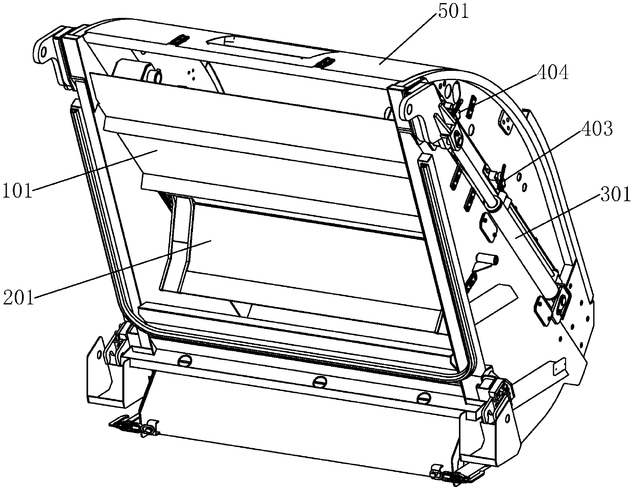
[0057] A filling device for a compressed garbage truck, such as Figures 1 to 3 As shown, it includes a housing 501 mounted on the opening of the garbage truck compartment, the motion device described in Embodiment 2, and a controller 401 for providing control functions of various mechanisms.

[0058] The two sides of the slider mechanism 101 installed in the housing 501 are slidingly connected to the left and right side walls of the housing 501 respectively, and protrude from the left and right side walls of the housing 501. The slider mechanism 101 is driven by the power mechanism to perform a reciprocating sliding motion. The direction is inclined from top to bottom from the front of the garbage truck to the rear.

[0059] Both the second sensor 403 and the third sensor 404 are installed on the same side wall or opposite different side walls of the filler, and are respectively located near the end point of the slide mechanism 101 sliding down and the position close to the e...


PUM


Abstract

The invention discloses an induction mechanism, a motion device and a motion system. At least two induction portions and a driving link generate linkage, and the different motion states of the drivinglink are indirectly inducted through induction of a first sensor to the different induction portions. Due to the fact that the first sensor can induct the different motion states of the driving link,the structure of the motion device is simplified, mutual interference between various components in the motion device is reduced, and especially interference to the sensor is reduced; then motion control is more precise and stable, continuity of component action is improved, and mechanical vibration caused by the mutual effect between mechanical structures is reduced; and therefore the service life of the components is prolonged, and the later maintenance cost of the system is reduced.

Description

technical field [0001] The invention relates to the technical field of motion control, in particular to an induction mechanism, an exercise device including the induction mechanism and an exercise system including the exercise device. Background technique [0002] The garbage compression mechanism of the rear-mounted compression garbage truck is mainly composed of two parts: a scraper mechanism and a slide mechanism. The compression mechanism works in the following order during the process of compressing garbage: four actions: opening of the scraper mechanism, downward movement of the slider mechanism, scraping of the scraper mechanism, and upward movement of the slider mechanism. These four actions constitute the working cycle of the compression mechanism to complete the garbage purpose of compression. The actions of the traditional scraper mechanism and slide mechanism are respectively driven by two sets of hydraulic cylinders, which are connected to the same hydraulic va...

Claims


Application Information

Patent Timeline
Patent Type & Authority Applications(China)
IPC IPC(8): F15B11/20F15B13/16F15B13/07B65F3/14
CPCF15B11/20B65F3/14B65F2003/146B65F2210/162B65F2210/168F15B13/07F15B13/16
Inventor 姚华军黄闯周聪杨忆周启君
Owner 深圳东风汽车有限公司
Why Eureka
Try Eureka