Infiltration and suction system for enhancing carbonated water under high temperature and high pressure conditions

A high-temperature, high-pressure, carbonized water technology, applied in the field of oil drilling engineering, can solve problems such as inability to simulate high-temperature and high-pressure conditions, design not in line with actual formation conditions, and high viscosity of crude oil

Active Publication Date: 2018-02-23
CHINA UNIV OF PETROLEUM (BEIJING)
View PDF3 Cites 10 Cited by
  • Summary
  • Abstract
  • Description
  • Claims
  • Application Information

AI Technical Summary

Problems solved by technology

The device drives the rock sample holder to rotate through the motor, and under the action of centrifugal force, the oil droplets adhering to the surface of the core are separated from the surface of the core and float into the measuring tube. Formation water is used as a fluid, and the viscosity of crude oil is still relatively high; the core in this device is rotating, but the core in the actual formation is fixed, so the design of the device does not conform to the actual formation conditions; in addition, the device is operated at normal temperature and pressure Experiments conducted under low temperature conditions cannot simulate the high temperature and high pressure conditions of the actual formation

Method used


Image

  • Infiltration and suction system for enhancing carbonated water under high temperature and high pressure conditions
  • Infiltration and suction system for enhancing carbonated water under high temperature and high pressure conditions
  • Infiltration and suction system for enhancing carbonated water under high temperature and high pressure conditions

Examples


Embodiment Construction

[0049] In order to further understand the content of the present invention, the present invention will be described in detail below in conjunction with specific examples.

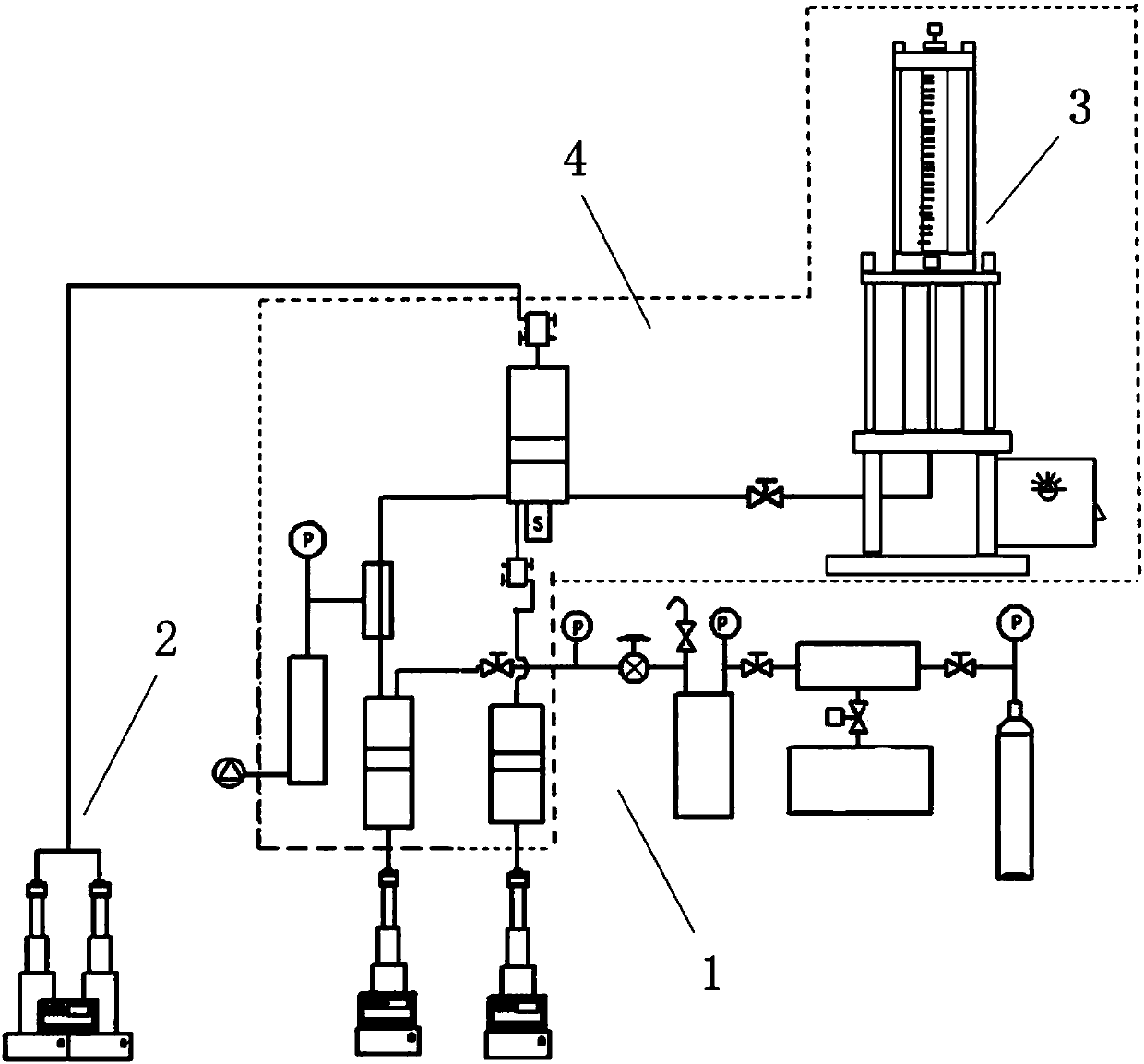
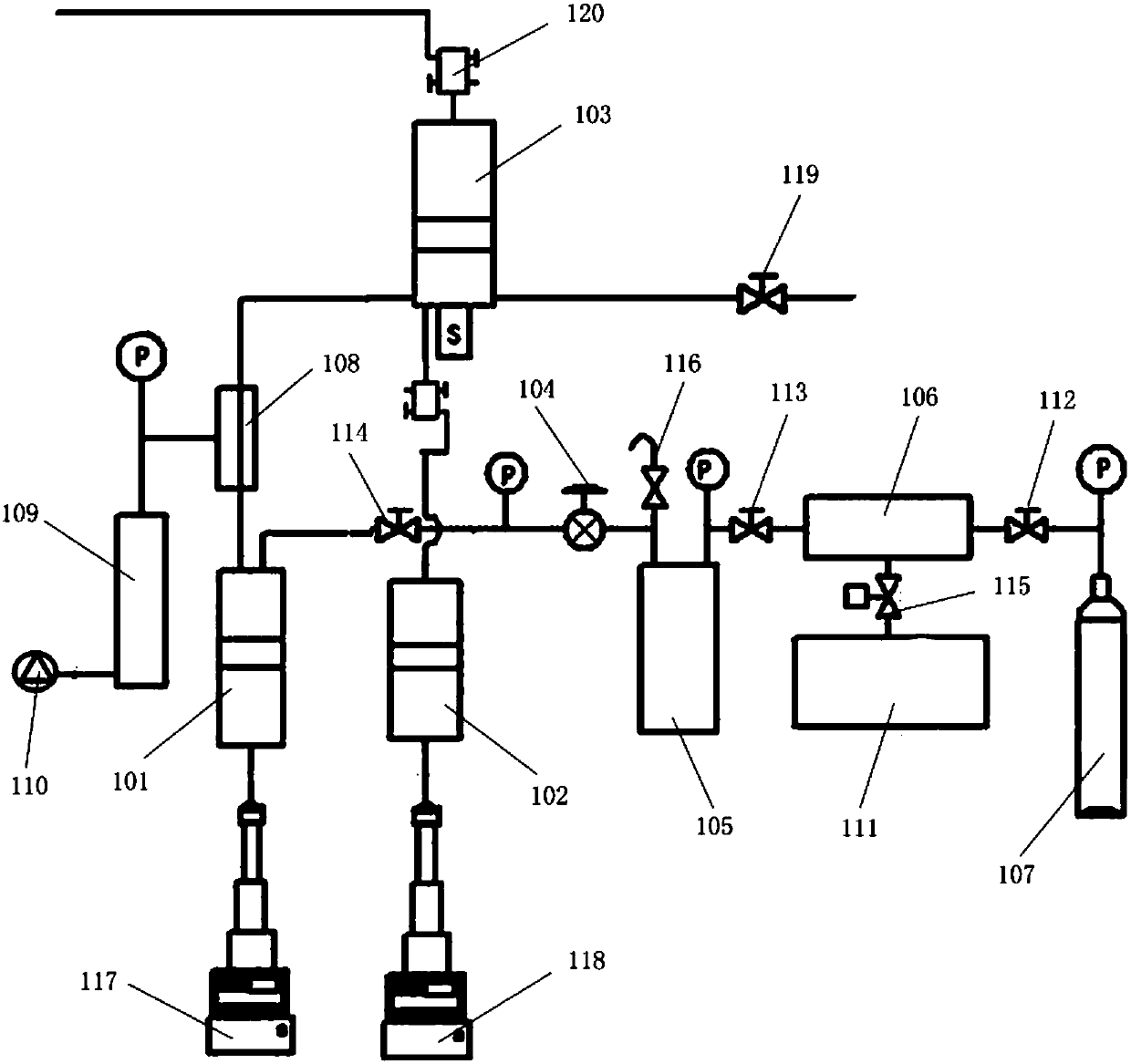
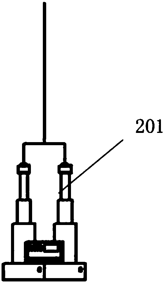
[0050] Such as Figure 1-5 Shown, according to an embodiment of the imbibition system of strengthening carbonized water under the high temperature and high pressure condition of the present invention, comprise the preparation system 1 of carbonated water, the injection system 2 of carbonated water and the imbibition system 3 of rock core, the osmosis system 3 of described carbonized water The preparation system 1 is connected with the imbibition system 3 of the rock core through a pipeline, and the injection system 2 of the carbonated water injects the carbonated water into the imbibition system 3 of the rock core; the carbonization in the imbibition system 3 of the rock core The water can rotate and flow, and the carbonized water is dissolved CO 2 of aqueous solution.

[0051] In this embodiment, carbonize...


PUM

PropertyMeasurementUnit
lengthaaaaaaaaaa
lengthaaaaaaaaaa

Abstract

The invention relates to an infiltration and suction system for enhancing carbonated water under high temperature and high pressure conditions. The infiltration and suction system comprises a carbonated water preparation system, a carbonated water injection system and a rock core infiltration and suction system; the carbonated water preparation system is connected with the rock core infiltration and suction system through a pipeline; the carbonated water injection system injects the carbonated water into the rock core infiltration and suction system; the carbonated water in the rock core infiltration and suction system can rotationally flow; and the carbonated water is an aqueous solution in which CO2 is dissolved. An electromotor is mounted in the infiltration and suction system, can drive a rotating plate and a rotating rod in a metal container to rotate and further drives a fluid to rotate, so that on one hand, the end surface at the lower par of a rock core cannot be shielded, andon the other hand, the infiltration and suction process of the rock core is accelerated, and therefore, the infiltration and suction period of the rock core is greatly shortened, and the infiltrationand suction efficiency is improved; and the fluid rotation and the rotating speed setting can aim at different types of rock cores and different types of crude oil, so that the phenomenon that oil droplets are adsorbed on the surface of the rock core is effectively eliminated.

Description

technical field [0001] The invention belongs to the technical field of petroleum drilling engineering, and in particular relates to an imbibition system for strengthening carbonized water under high temperature and high pressure conditions. Background technique [0002] In low permeability, ultra-low permeability, tight oil reservoirs and carbonate rock reservoirs, there are different degrees of fracture development. The seepage system in this oil reservoir includes fracture system and matrix system. The production mechanism of these oil reservoirs is as follows: when the injected water enters the formation, the oil in the fractures will be displaced first, and the water saturation of the fractures will increase, so that there will be a problem between the fractures and the bedrock due to the difference in saturation. At this time, relying on the action of capillary force, the injected water enters the bedrock and the oil is discharged from the bedrock into the fractures. Th...

Claims


Application Information

Patent Timeline
Patent Type & Authority Applications(China)
IPC IPC(8): G01N15/08
CPCG01N15/08G01N15/0806
Inventor 于海洋刘俊辉程时清芦鑫
Owner CHINA UNIV OF PETROLEUM (BEIJING)
Why Eureka
Try Eureka