Driving method of display panel, display panel and display device

A technology of a display panel and a driving method, applied in the input/output process of data processing, instruments, calculations, etc., can solve problems such as affecting display quality, abnormal display of display images, and large impact on common electrodes.

Active Publication Date: 2020-07-28
WUHAN TIANMA MICRO ELECTRONICS CO LTD
View PDF7 Cites 0 Cited by
  • Summary
  • Abstract
  • Description
  • Claims
  • Application Information

AI Technical Summary

Problems solved by technology

[0004] However, since the data lines are floating during the touch phase, other structures, such as touch signal lines, interfere with the data lines, and the data lines will have potential drift due to the influence of other structures, and the touch phase ends and enters the next display. During the stage, the data line inputs the display signal, and the voltage on the data line will have a larger deviation than the actual received display signal voltage due to potential drift during the time just entering the display stage, and this deviation is uncontrollable, and It will have an impact on the common electrode; in addition, when the touch phase ends and enters the next display phase, the data line changes from a floating state to an input display signal state, which will also have an impact on the common electrode. In general, as image 3 In the stage shown in the area B in the center, the impact on the common electrode is relatively large, and it is uncontrollable. At this time, the corresponding liquid crystal cannot be deflected to the preset angle, resulting in abnormal display on the display screen, such as abnormal horizontal line, affecting display quality

Method used


Image

  • Driving method of display panel, display panel and display device
  • Driving method of display panel, display panel and display device
  • Driving method of display panel, display panel and display device

Examples


Embodiment Construction

[0031] In order to make the above objects, features and advantages of the present invention more comprehensible, the present invention will be further described below in conjunction with the accompanying drawings and embodiments.

[0032] It should be noted that in the following description, specific details are set forth in order to fully understand the present invention. However, the present invention can be implemented in many other ways than those described here, and those skilled in the art can make similar extensions without departing from the connotation of the present invention. Accordingly, the present invention is not limited to the specific embodiments disclosed below.

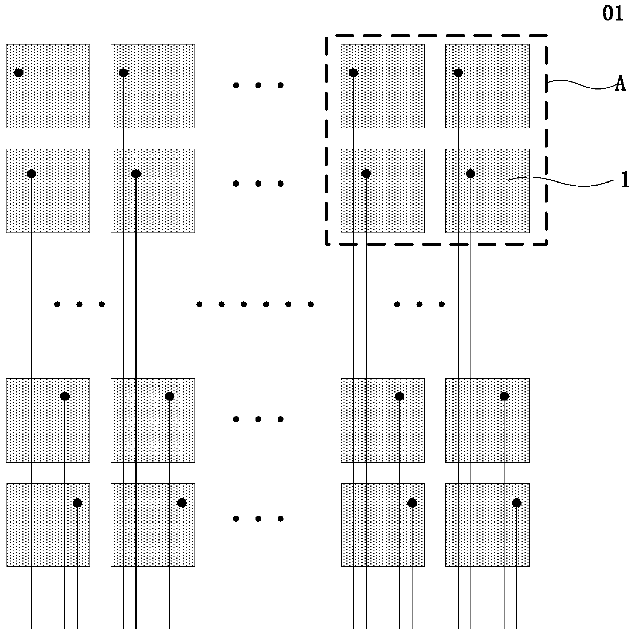
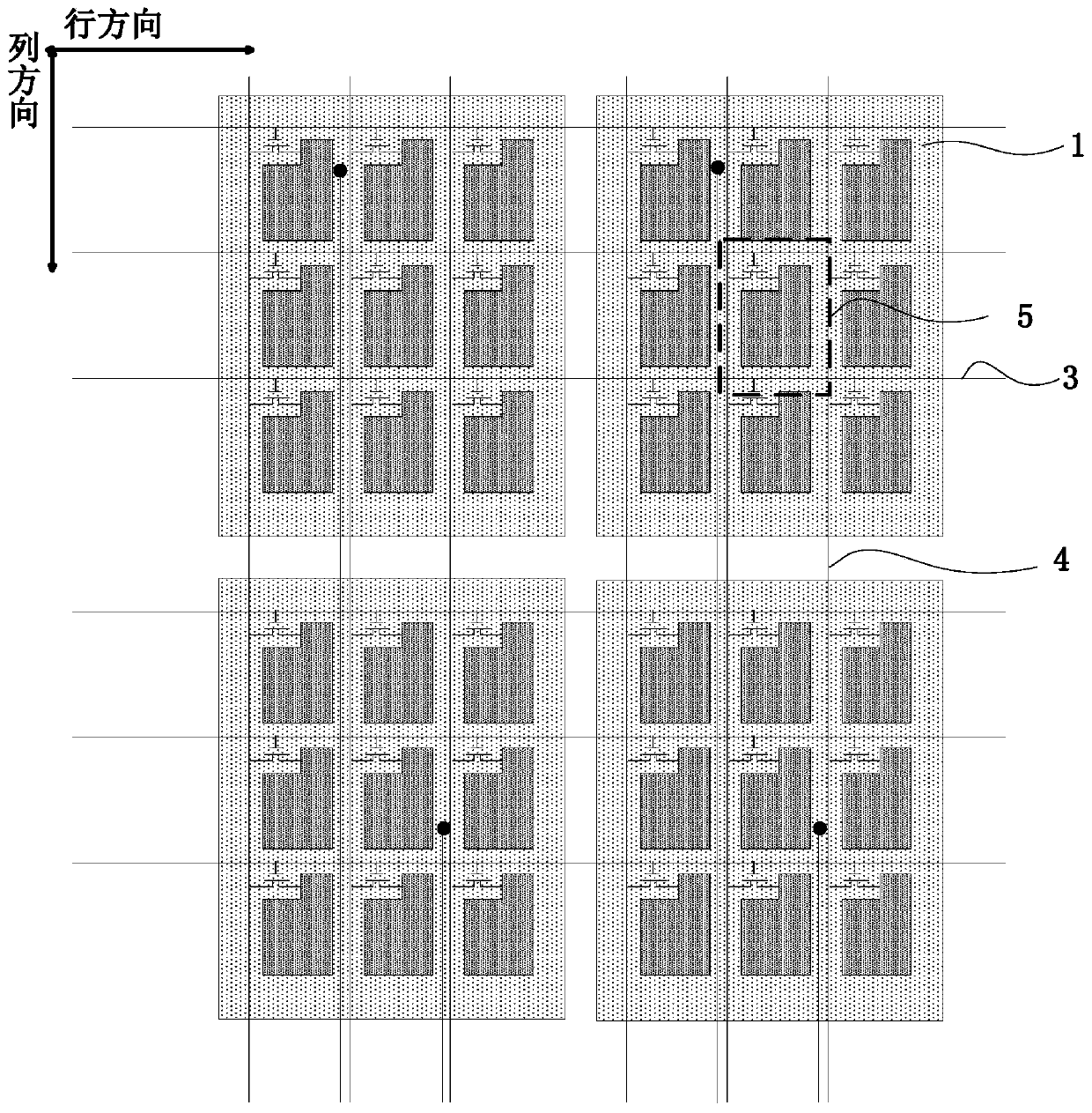
[0033] An embodiment of the present invention provides a method for driving a display panel. The display panel includes a plurality of gate lines extending along the row direction and arranged in the column direction, and a plurality of data lines extending in the column direction and arranged in th...


PUM


Abstract

The embodiment of the invention provides a driving method for a display panel, a display panel and a display device. The driving method for the display panel comprises steps that the display panel comprises at least two display phases and at least two touch control phases when displaying each frame image; the display phases and the touch control phases are alternatively arranged; in the touch control phase, a public electrode is used as a touch control electrode; each touch control electrode receives a touch control signal and a grid line is suspended; in the display phase, a part of grid lines receives a scanning signal, each data line receives a display signal and the public electrode receives a public voltage signal; the touch control phase has a pre-displaying phase and the data line in the pre-displaying phase receives a preset signal; the pre-displaying phase of the touch control phase is adjacent to the display phase in the orderly-adjacent touch control phases and the display phases. A possibility of display abnormity due to impact of the public electrode can be effectively reduced, so display quality can be improved.

Description

technical field [0001] The present invention relates to the field of display technology, in particular to a driving method of a display panel, a display panel and a display device. Background technique [0002] In order to better meet user needs, the display panel is no longer limited to the display function, but also integrates a touch function on the basis of the display to form a touch display panel. [0003] The current touch display panel includes a plurality of common electrodes arranged in an array. The working phase of the display panel includes a display phase and a touch phase, wherein the display phase and the touch phase are performed alternately. In the touch phase, the common electrodes are multiplexed. for touch electrodes. Specifically, such as Figure 1 to Figure 3 as shown, figure 1 It is a structural schematic diagram of a display panel in the prior art, figure 2 yes figure 1 The enlarged view of the region A in the middle, image 3 yes figure 1...

Claims


Application Information

Patent Timeline
Patent Type & Authority Patents(China)
IPC IPC(8): G02F1/1333G02F1/1362G02F1/1343G06F3/041
CPCG02F1/13338G02F1/134309G02F1/136286G06F3/0412
Inventor 赖青俊
Owner WUHAN TIANMA MICRO ELECTRONICS CO LTD
Why Eureka
Try Eureka