A 3D-based energy equipment monitoring method and system
What is AI technical title?
AI technical title is built by PatSnap AI team. It summarizes the technical point description of the patent document.
A device monitoring and 3D technology, applied in 3D modeling, digital output to display equipment, data processing input/output process, etc., to achieve good real-time performance, convenient implementation, good reusability and portability
Active Publication Date: 2021-10-01
SHANGHAI ELECTRIC DISTRIBUTED ENERGY TECH CO LTD
View PDF6 Cites 0 Cited by
Summary
Abstract
Description
Claims
Application Information
AI Technical Summary
This helps you quickly interpret patents by identifying the three key elements:
Problems solved by technology
Method used
Benefits of technology
Problems solved by technology
However, the above technology is only for the simulated 3D display of the wind turbines in the centralized wind farm, and is not suitable for the combination of centralized photovoltaic power plants and distributed new energy equipment
Method used
Image
Click on the blue label to locate the original text in one second.
Reading with bidirectional positioning of images and text.
Examples
Embodiment 1
[0117] Step1: Use 3D design software (such as SolidWorks) to disassemble and model the fan, and design each component of the fan in turn, including: blades, hubs, main shafts, nacelles and towers, etc., to form multiple component files (such as blade 1.SLDPRT) ;
[0118] Step2: Assemble and merge the components of each fan into an assembly (such as fan.SLDASM), and then export the assembly as a fan model file (such as fan_old.xaml);
[0119] Step3: Optimize the exported fan model file, and use the defined model template to generate an optimized model file (such as fan.xaml);
[0120] Step4: Create an interface of a 3D model, and define the general properties of the interface (such as display size, background color, and device type, etc.) and general operation methods (such as pressing the left button, selecting and moving, etc.);
[0121] Step5: Create a class for the fan equipment model, and define the properties of the class (such as current angle, rotation speed and rotati...
Embodiment 2
[0141] Step1: Use 3D design software (such as SolidWorks) to disassemble and model the lithium battery, and design each component of the lithium battery in turn, including: box, hinge, cover, upper baffle and lower baffle, etc., to form multiple component files (such as box.SLDPRT);
[0142] Step2: Assemble and merge the components of each lithium battery into an assembly (such as lithium battery.SLDASM), and then export the assembly as a lithium battery model file (such as lithium battery_old.xaml);
[0143] Step3: Optimize the exported lithium battery model file, and use the defined model template to generate an optimized model file (such as lithium battery.xaml);
[0144] Step4: Create an interface of a 3D model, and define the general properties of the interface (such as display size, background color, and device type, etc.) and general operation methods (such as pressing the left button, selecting and moving, etc.);
[0145] Step5: Create a class for the lithium battery ...
PUM
Abstract
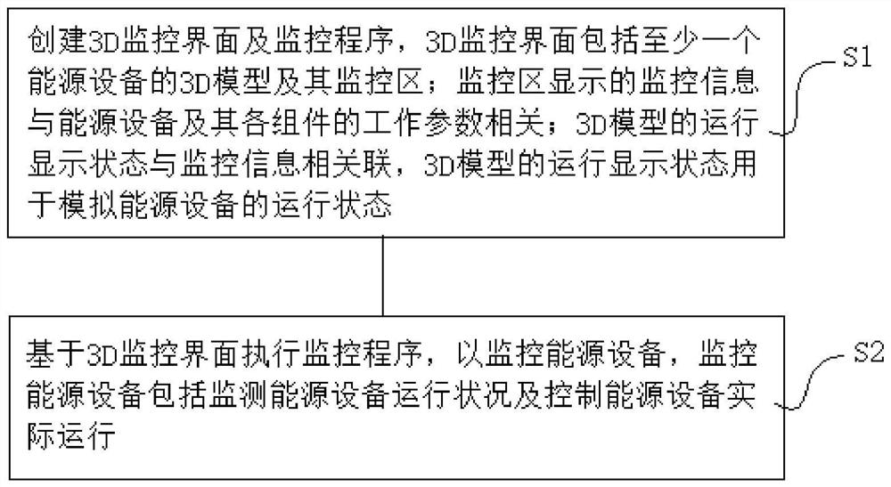
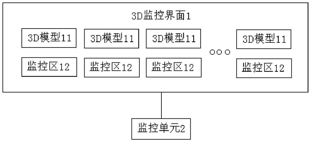
The invention discloses a 3D-based energy equipment monitoring method and system. The method includes the following steps: creating a 3D monitoring interface and a monitoring program, the 3D monitoring interface including at least one energy equipment 3D model and its monitoring area; wherein, the monitoring The monitoring information displayed in the area is related to the working parameters of the energy equipment and its components; the running display state of the 3D model is associated with the monitoring information, and the running display state of the 3D model is used to simulate the running state of the energy equipment; The monitoring program is executed based on the 3D monitoring interface to monitor the energy equipment, and the monitoring of the energy equipment includes monitoring the operation status of the energy equipment and controlling the actual operation of the energy equipment. The implementation method of the general interface display provided by the present invention is applicable to various devices and various occasions; the resource files generated by the application program displaying the interface in the present invention can be independent of the program, thereby being reused by other programs based on the .NET environment .
Description
technical field [0001] The invention relates to the field of equipment real-time monitoring, in particular to a 3D-based energy equipment monitoring method and system. Background technique [0002] With the increasingly prominent environmental and resource issues, the utilization of renewable resources and new energy equipment have been continuously developed. Usually large-scale photovoltaic power plants, wind farms, energy storage power plants, etc. are located in remote areas, and all kinds of information about all their power equipment and new energy equipment need to be uploaded to the monitoring center through communication. It is impossible to obtain the internal operation problems of the equipment just by installing the camera, and the camera installed outdoors will be damaged quickly due to environmental problems, so a large number of workers need to be deployed on site, which not only wastes time, but also increases a lot of unnecessary problems. necessary expense...
Claims
Application Information
Patent Timeline
Application Date:The date an application was filed.
Publication Date:The date a patent or application was officially published.
First Publication Date:The earliest publication date of a patent with the same application number.
Issue Date:Publication date of the patent grant document.
PCT Entry Date:The Entry date of PCT National Phase.
Estimated Expiry Date:The statutory expiry date of a patent right according to the Patent Law, and it is the longest term of protection that the patent right can achieve without the termination of the patent right due to other reasons(Term extension factor has been taken into account ).
Invalid Date:Actual expiry date is based on effective date or publication date of legal transaction data of invalid patent.
Patent Type & AuthorityPatents(China)
IPC IPC(8): G06F3/14G06T17/00
CPCG06F3/1407G06T17/00
Inventor陈锋夏耀杰刘伟吕楠许泽阳
OwnerSHANGHAI ELECTRIC DISTRIBUTED ENERGY TECH CO LTD

