Fixing device for steel bar cutting

A technology of fixing device and steel bar, applied in the direction of grinding/polishing safety device, grinding workpiece support, grinder, etc. Effect

Active Publication Date: 2018-02-27
ZHEJIANG ROAD & BRIDGE CONSTR
View PDF8 Cites 1 Cited by
  • Summary
  • Abstract
  • Description
  • Claims
  • Application Information

AI Technical Summary

Problems solved by technology

The device for fixing the steel bar of the grinding wheel cutting machine is composed of a fixed flat steel plate and a movable flat steel plate. Since the contact surface is flat, it is difficult to fix the round steel bar well, and the movable plate requires the worker to lean down and rotate frequently. If the distance between the screw and the screw is moved, not only the fixing effect is poor, but the end surface of the steel bar is uneven, which affects the quality of the steel bar connection, and it is time-consuming and labor-intensive. At the same time, there are safety hazards such as the steel bar slipping off and the cutting piece breaking and hurting people.

Method used


Image

  • Fixing device for steel bar cutting
  • Fixing device for steel bar cutting
  • Fixing device for steel bar cutting

Examples


Embodiment

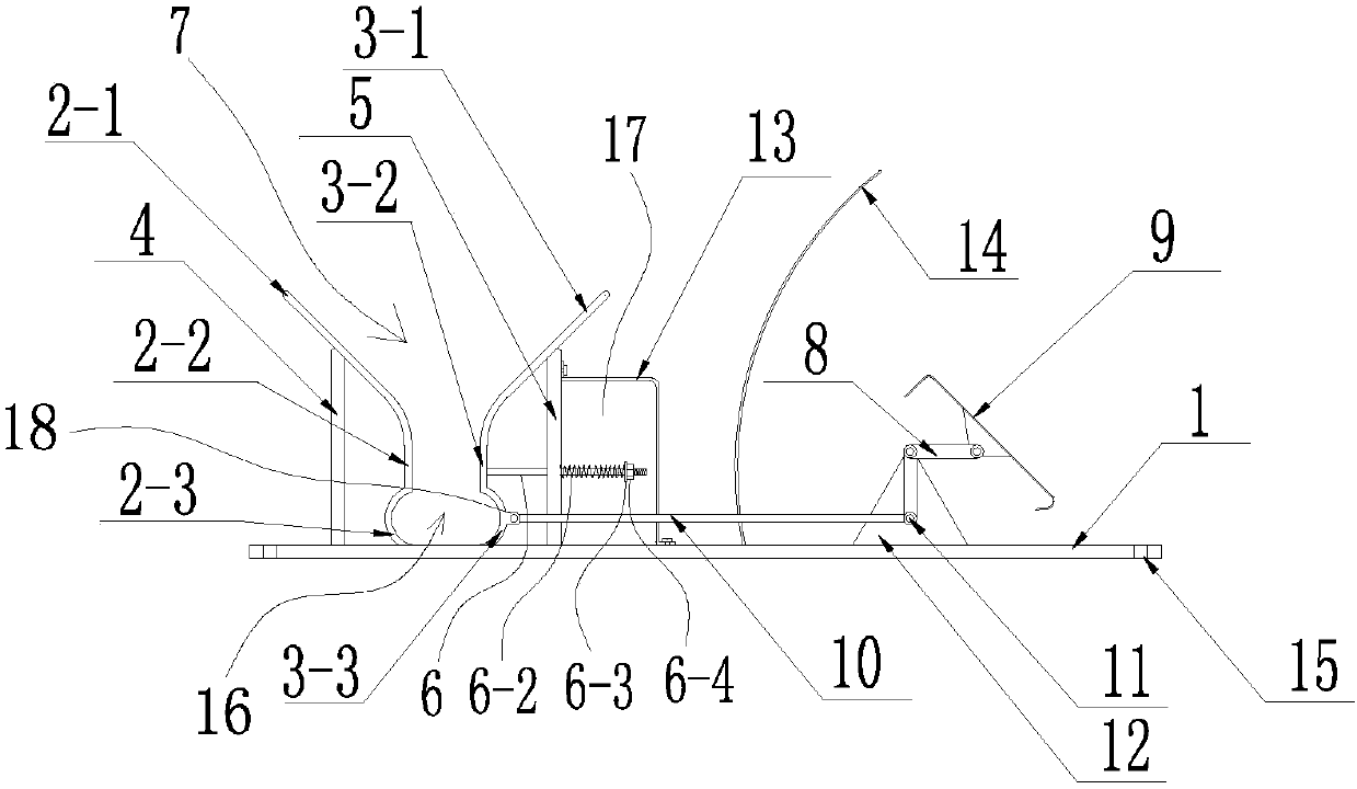
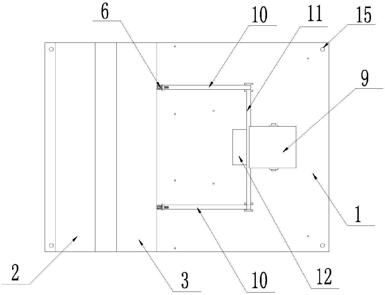
[0025] Example: such as Figure 1-3 As shown, the steel bar cutting and fixing device of the present application includes a bottom plate 1; the bottom plate 1 is a flat steel plate, and the upper surface of the bottom plate 1 is oppositely arranged with a fixed splint 2 and a movable splint 3; the fixed splint 2 is fixed on the bottom plate 1, and the lower end Welded on the flat steel plate 1, the movable splint 3 is movably arranged on the bottom plate 1, and the four corners of the flat steel plate 1 have four mounting holes 15, which are fixed on the cutting machine with bolts; the bottom of the fixed splint 2 and the movable splint 3 are provided with positioning for fixing steel bars Groove 16, the shape of the positioning groove 16 matches the shape of the steel bar, which can closely adhere to and firmly clamp the round steel bar, so that the cut end face of the steel bar is flush and perpendicular to the longitudinal axis of the steel bar; the movable splint 3 is provi...


PUM


Abstract

The invention relates to a fixing device for steel bar cutting. The fixing device for steel bar cutting comprises a base plate. A fixed clamping plate and a movable clamping plate are oppositely arranged on the upper surface of the base plate. The fixed clamping plate is fixedly arranged on the base plate. The movable clamping plate is movably arranged on the base plate. Positioning grooves sued for fixing steel bars are formed in the bottom of the fixed clamping plate and the bottom of the movable clamping plate. A guiding device and a transmission device are arranged outside the movable clamping plate. The transmission device drives the movable clamping plate to move front and back in the length direction of the base plate through the guiding device and is used for clamping or releasingsteel bars. The upper portion of a guiding groove formed by the fixed clamping plate and the movable clamping plate inclines outwards to be in a funnel shape, so that a guiding function is achieved, and steel bars can be placed in the guiding groove conveniently. The lower end of a positioning groove formed by the fixed clamping plate and the movable clamping plate is round and can tightly and firmly clamp round steel bars, and thus the end faces of the steel bars are made flush and perpendicular to the longitudinal axes of the steel bars.

Description

technical field [0001] The invention relates to the technical field of steel bar cutting and processing, in particular to a steel bar cutting and fixing device. Background technique [0002] In civil engineering construction, the mechanical connection process of upsetting straight threads of steel bars is currently mostly used. In order to ensure the uniform diameter of the upsetting parts of the steel bars and the integrity of the processed thread threads, it is required that the cutting end faces of the steel bars be strictly flush in addition to being round, that is, the end faces perpendicular to the longitudinal axis of the bar. In order to meet this requirement, grinding wheel cutters are generally used on construction sites to cut steel bars. The device for fixing the steel bar of the grinding wheel cutting machine is composed of a fixed flat steel plate and a movable flat steel plate. Since the contact surface is flat, it is difficult to fix the round steel bar well...

Claims


Application Information

Patent Timeline
Patent Type & Authority Applications(China)
IPC IPC(8): B24B41/06B24B55/04B24B27/06
CPCB24B27/0683B24B41/067B24B55/04
Inventor 陈叶刚金龙林韦麟林后宽陈英杰胡继强徐建国
Owner ZHEJIANG ROAD & BRIDGE CONSTR
Why Eureka
Try Eureka