Automatic double-shaft position correction device

An automatic, motor-driven circuit technology, applied in the direction of using feedback control, closed-circuit television system, etc., can solve the problems of image shaking, inability to effectively monitor the position, and the inability of the pan/tilt to return, and achieve the effect of improving absolute accuracy

Inactive Publication Date: 2018-02-27
HANGZHOUSR ELECTRONICS
View PDF4 Cites 9 Cited by
  • Summary
  • Abstract
  • Description
  • Claims
  • Application Information

AI Technical Summary

Problems solved by technology

[0002] Ordinary pan/tilt call preset position technology: when the pan/tilt moves to a certain position, it can save the above position, and when it needs to observe the above position again, it can call the preset position saved in advance to return to the above position, because the stepping motor has no Feedback mechanism, so this preset position is a relative position; if the gimbal is installed on a fixed object, when the external environment is harsh (such as strong wind) and t

Method used


Image

  • Automatic double-shaft position correction device

Examples


Embodiment 1

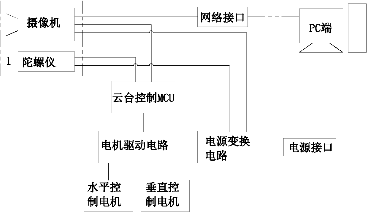
[0008] Embodiment 1: refer to figure 1 . A dual-axis position automatic correction device, including PC terminal, camera, gyroscope, PTZ control MCU, motor drive circuit, horizontal control motor, vertical control motor, power conversion circuit, power interface, network interface, camera, gyroscope They are respectively electrically connected to the pan-tilt control MCU, and the pan-tilt control MCU is electrically connected to the motor drive circuit. The control terminals of the horizontal control motor and the vertical control motor are respectively controlled and connected by the motor drive circuit, and the power conversion circuit will be input through the power interface. The power supply is converted into DC power supply to the camera, gyroscope, pan-tilt control MCU and motor drive circuit, and the camera communicates with the PC through the network interface. The dual-axis position automatic correction device also includes a camera installation compartment 1 for in...


PUM


Abstract

The invention relates to an automatic double-shaft position correction device. The device is characterized by comprising a PC end, a video camera, a gyroscope, a head control MCU, a motor driving circuit, a horizontal control motor, a vertical control motor, a source transformation circuit, a power supply interface and a network interface. The video camera and the gyroscope are electrically connected with the head control MCU separately, the head control MCU is electrically connected with the motor driving circuit, and the control end of the horizontal control motor and the control end of thevertical control motor are in control connection with the motor driving circuit separately. By means of the automatic double-shaft position correction device, it can be achieved that a preset positionis automatically corrected, data is collected by using the gyroscope, the current absolute attitude position and the relative deviation angle of a head are calculated, and a control signal is sent bythe head control MCU to the motor driving circuit, so that the horizontal control motor and the vertical control motor are controlled, the horizontal and vertical angles of the head are compensated,and the defects are overcome that when calling the preset position, an ordinary head is disturbed by the outside, so that the position of the head video camera is changed, and the head video camera cannot return to the original preset position.

Description

technical field [0001] The invention relates to the field of video monitoring devices, in particular to a device for automatically correcting biaxial positions. Background technique [0002] Ordinary pan / tilt call preset position technology: when the pan / tilt moves to a certain position, it can save the above position, and when it needs to observe the above position again, it can call the preset position saved in advance to return to the above position, because the stepping motor has no Feedback mechanism, so this preset position is a relative position; if the gimbal is installed on a fixed object, when the external environment is harsh (such as strong wind) and the jitter is relatively large, the position of the gimbal will be shifted due to external influences, resulting in The pan / tilt cannot return to the accurate preset position; if the pan / tilt is installed on a moving carrier (such as a vehicle, ship), the position of the pan / tilt is changed due to large shakes or sha...

Claims


Application Information

Patent Timeline
IPC IPC(8): G05D3/12H04N7/18
CPCG05D3/12H04N7/18
Inventor 傅清新陶连日许林
Owner HANGZHOUSR ELECTRONICS
Why Eureka
Try Eureka