Astronavigation distributed power supply system cascade stability control method and implementation device

A technology of distributed power supply and stability control, applied in control/regulation systems, output power conversion devices, electrical components, etc., can solve problems such as slow response speed, low tracking accuracy, and reduced reliability of spacecraft power supply, etc. Achieving the effect of fast response speed, ensuring power supply quality and good power supply quality

Pending Publication Date: 2022-03-15
BEIJING SATELLITE MFG FACTORY
View PDF0 Cites 1 Cited by
  • Summary
  • Abstract
  • Description
  • Claims
  • Application Information

AI Technical Summary

Problems solved by technology

Therefore, the current control method has slow response speed and low tracking accuracy
On the one hand, when the front-stage converter encounters an abnormal disturbance, the current control method needs to go through the output change of the intermediate converter before the abnormal disturbance can be fed back to the controller, and it is impossible to quickly cut off the abnormal impact of the front-stage converter. The interference of the bus voltage of the spacecraft will affect the power supply quality of the primary bus voltage of the spacecraft in severe cases, reducing the reliability of the power supply of the spacecraft
On the other hand, due to the rapid changes in the load of the spacecraft and the energy demand of the electrical equipment, the output energy of the load converter changes greatly. The current control method is still unable to respond in a timely and accurate manner, and it is easy to cause the load to fail to work normally for a long time.

Method used


Image

  • Astronavigation distributed power supply system cascade stability control method and implementation device
  • Astronavigation distributed power supply system cascade stability control method and implementation device
  • Astronavigation distributed power supply system cascade stability control method and implementation device

Examples


Embodiment Construction

[0042] In order to more clearly describe the embodiments of the present invention or the technical solutions in the prior art, the following will briefly introduce the drawings that are used in the embodiments. Apparently, the drawings in the following description are only some embodiments of the present invention, and those skilled in the art can also obtain other drawings according to these drawings without creative efforts.

[0043] The present invention will be described in detail below in conjunction with the accompanying drawings and specific embodiments, and the embodiments cannot be repeated here one by one, but the embodiments of the present invention are not therefore limited to the following embodiments.

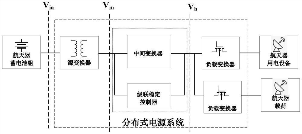
[0044] figure 1 An application scene diagram of an aerospace distributed power system cascade stability control method provided by an embodiment of the present invention. In the aerospace distributed power supply system, the primary bus is provided by the solar phot...


PUM


Abstract

The invention relates to the technical field of aerospace secondary power supplies, and discloses an aerospace distributed power supply system cascade stability control method and an implementation device. In an astronavigation distributed power supply system, a mathematical model of an intermediate converter, an expected value Vo * of the output voltage and an expected value IL * of the output current are obtained by obtaining an output voltage Vm of a source converter, an input voltage Vb and an input current Ib of a load converter, and an output voltage uo and an inductive current IL of the intermediate converter, and according to a controller established based on a PCHD equation, the output voltage Vo * of the intermediate converter and the expected value IL * of the output current are calculated. And controlling the intermediate converter. Due to the fact that the controlled quantity of the controlled intermediate converter is jointly determined by the state quantities of all the converters in the distributed system, the response speed and accuracy of the aerospace distributed power supply system to disturbance of all links are greatly improved, and the cascading stability of the aerospace distributed power supply system is improved.

Description

technical field [0001] The invention relates to the technical field of aerospace secondary power supplies, in particular to a cascade stability control method and implementation device for an aerospace distributed power supply system. Background technique [0002] In recent years, in order to reduce the power supply loss of the aerospace power system and improve the efficiency and power supply flexibility of the power system, the aerospace secondary power supply system has gradually changed from the traditional single-stage power supply architecture to a two-stage distributed power supply system architecture. The aerospace distributed power system consists of at least one source converter cascaded with a load converter. Among them, the source converter realizes the first voltage conversion, and at the same time isolates the power system from the spacecraft power supply bus to avoid catastrophic failure of the bus voltage due to power system failure. The load converter realiz...

Claims


Application Information

Patent Timeline
Patent Type & Authority Applications(China)
IPC IPC(8): H02M3/158
CPCH02M3/158
Inventor 唐骐谢鹏飞刘密陈永刚胡忠阳
Owner BEIJING SATELLITE MFG FACTORY
Why Eureka
Try Eureka