
Telescopic indoor ceiling lamp

A chandelier and light strip technology, applied in lighting devices, fixed lighting devices, electric light sources, etc., can solve the problems of inability to adjust the light in individual areas, unable to change patterns, etc., and achieve the effect of preventing aesthetic fatigue and reasonable structure design.

Inactive Publication Date: 2018-03-02
何雅楠
View PDF0 Cites 2 Cited by
  • Summary
  • Abstract
  • Description
  • Claims
  • Application Information

AI Technical Summary

Problems solved by technology

[0003] The shape of the existing chandelier is generally fixed after installation, and the pattern cannot be changed; and once the installation is completed, the area illuminated by it is also fixed, and the light cannot be adjusted for individual areas according to the needs of users.

Method used


Image

  • Telescopic indoor ceiling lamp
  • Telescopic indoor ceiling lamp
  • Telescopic indoor ceiling lamp

Examples


Embodiment 1

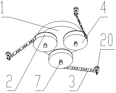
[0035] see Figure 1-8 , The embodiment of the present invention provides a retractable indoor chandelier, including a fixed support plate 1, three lamp panels 2 arranged symmetrically along the center of the fixed support plate 1, and a light strip 3 that can be stretched in the lamp panel 2.

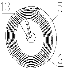
[0036] The lamp panel 2 includes a cylindrical outer shell 4, a rotating disk 5 arranged in the outer shell 4, and a clockwork spring 6;

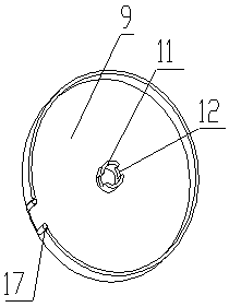
[0037] The outer casing 4 includes a lower bottom plate 9, an annular side wall arranged around the lower bottom plate 9 and an upper bottom plate 8 connected with the annular side wall by screws, a retractable opening 10 is arranged on the side wall, and a column 11 is arranged at the center of the upper end surface of the lower bottom plate 9 , the lower bottom surface of the column 11 is fixedly connected with the lower bottom plate 9;

[0038] The rotating disk 5 is composed of a disk 14 sleeved on the outside of the column 11 and a support rin...

Embodiment 2

[0054] see Figure 1-7 and Figure 9 , The embodiment of the present invention provides a retractable indoor chandelier, including a fixed support plate 1, five lamp panels 2 arranged symmetrically along the center of the fixed support plate 1, and a light strip 3 that can be stretched in the lamp panel 2.

[0055] The lamp panel 2 includes a cylindrical outer shell 4, a rotating disk 5 arranged in the outer shell 4, and a clockwork spring 6;

[0056] The outer casing 4 includes a lower bottom plate 9, an annular side wall arranged around the lower bottom plate 9 and an upper bottom plate 8 connected with the annular side wall by screws, a retractable opening 10 is arranged on the side wall, and a column 11 is arranged at the center of the upper end surface of the lower bottom plate 9 , the lower bottom surface of the column 11 is fixedly connected with the lower bottom plate 9;

[0057] The rotating disk 5 is composed of a disk 14 sleeved on the outside of the column 11 and...


PUM


Abstract

The invention discloses a retractable indoor chandelier, which comprises a fixed support plate, several lamp panels arranged symmetrically along the center of the fixed support plate, and a lamp strip that can be stretched in the lamp panel. The beneficial effects of the present invention are: the structural design of the present invention is reasonable, the lighting light in a local area can be temporarily changed according to the user's own needs through the stretching and retracting of the light strip in the lamp panel, and the pattern of the chandelier can also be changed according to the need, preventing the traditional The inability to change the style causes long-term aesthetic fatigue.

Description

technical field [0001] The invention relates to the field of lighting devices, in particular to a retractable indoor chandelier. Background technique [0002] Pendant lamps refer to high-end decorative lighting lamps that are suspended on the indoor ceiling, and all hanging lamps are classified into the pendant lamp category. There are the most patterns of chandeliers, commonly used are European-style candlestick chandeliers, Chinese-style chandeliers, crystal chandeliers, parchment chandeliers, fashion chandeliers, conical cover lanterns, pointed flat cover lanterns, waist cover lanterns, five-pronged ball chandeliers, magnolia cover lanterns, Olive chandelier, etc., the chandelier is suitable for living room, bedroom, restaurant, corridor, hotel and other lobbies. [0003] The shape of the existing chandelier is generally fixed after installation, and the pattern cannot be changed; and once the installation is completed, the area illuminated by it is also fixed, and the l...

Claims


Application Information

Patent Timeline
IPC IPC(8): F21S8/06F21V21/14F21V21/22
CPCF21S8/065F21S8/061F21V21/14F21V21/22
Inventor 何雅楠
Owner 何雅楠
Learn More