Automatic stamping system and method for cylinder part with automatic unloading function

A technology for automatic unloading and cylindrical parts, which is applied in the field of mechanical processing and stamping manufacturing, can solve the problems of complex process and low production efficiency of non-standard stainless steel cylinders, and achieve the effect of ensuring quality and solving inconvenient unloading.

Inactive Publication Date: 2018-03-06
巴中市新越不锈钢有限公司
View PDF7 Cites 12 Cited by
  • Summary
  • Abstract
  • Description
  • Claims
  • Application Information

AI Technical Summary

Problems solved by technology

[0003] The purpose of the present invention is to overcome the deficiencies of the prior art. The purpose is to provide an automatic stamping system and stamping method for cylindrical parts with automatic unloading function, so as to solve the problems of low production efficiency and complicated process of non-standard stainless steel cylinders.

Method used


Image

  • Automatic stamping system and method for cylinder part with automatic unloading function
  • Automatic stamping system and method for cylinder part with automatic unloading function

Examples


Embodiment 1

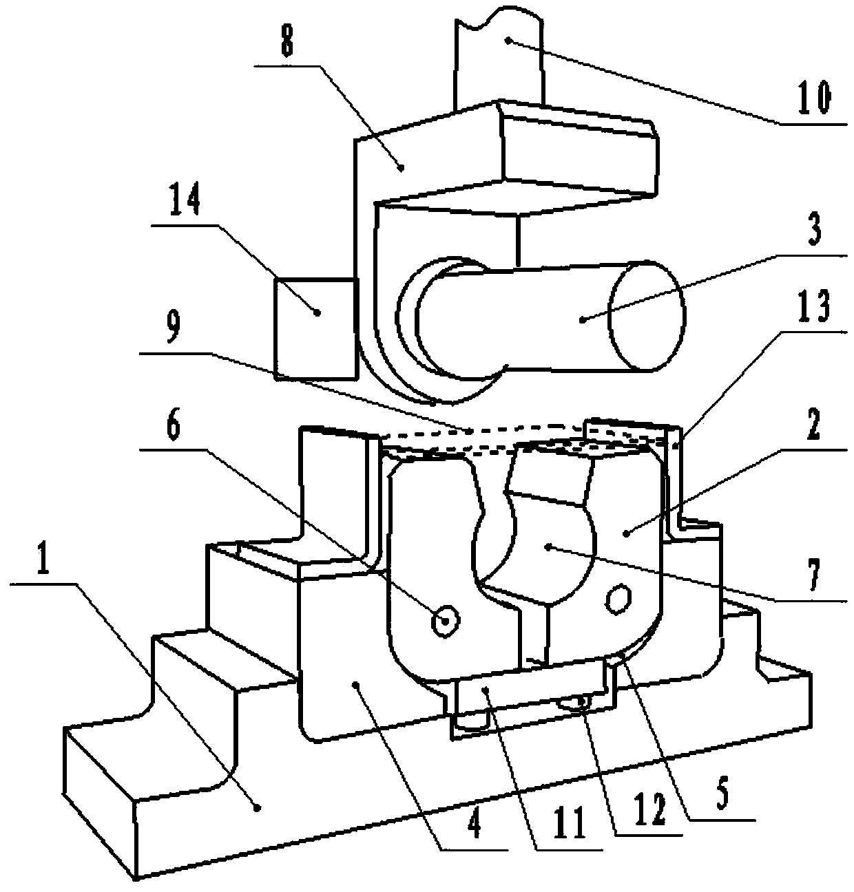
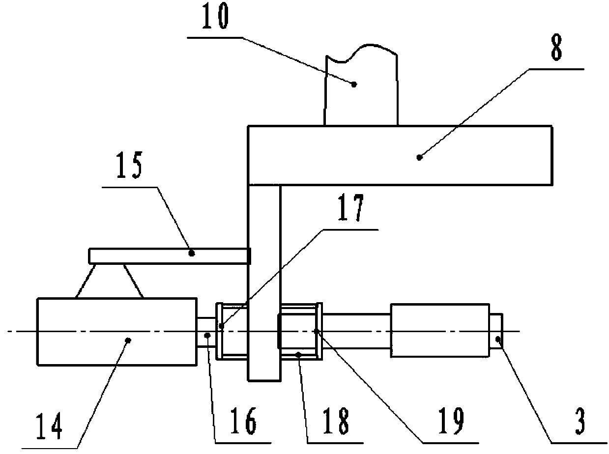
[0033] Such as Figure 1-2 As shown, an automatic stamping system for cylindrical parts with automatic unloading function of the present invention includes a stamping base 1, a stamping female module 2 and a stamping male die rod 3, and two stamping limit blocks 4 are symmetrically arranged on the stamping base 1 , the inner surface of the stamping limit block 4 is provided with a limit arc surface 5, and the two stamping female modules 2 are correspondingly arranged on the limit arc surfaces 5 of the two stamping limit blocks 4 through the limit shaft 6, and the stamping The inner surface of the mother module 2 is provided with an arc surface 7 matching the outer circle size of the stamping cylinder;

[0034] The stamping male die rod 3 is horizontally arranged on the corresponding top of the stamping base 1 and connected with the stamping block 8, and the rear side of the stamping block 8 corresponding to the stamping male die rod 3 is provided with a discharge cylinder 14, ...

Embodiment 2

[0042] Such as Figure 1-2 As shown, a kind of automatic stamping method of stainless steel cylindrical part of the present invention comprises steps:

[0043] Step 1) Place the cut stamping plate 9 between two L-shaped stamping plate stoppers;

[0044] Step 2) Then start the stamping bed to drive the stamping arm 10 to stamp downward, and the stamping arm 10 drives the stamping male die rod 3 to stamp the stamping plate 9;

[0045] Step 3) Punching the male mold rod 3 by putting the stamping plate 9 into the two stamping female modules 2 to form a cylindrical mold, and under the stamping action of the stamping male mold rod 3, the stamping female module 2 rotates around the limit shaft 6;

[0046] Step 4) When the upper end faces of the two stamped female modules 2 are connected, the stamped plate 9 is stamped into a cylindrical piece.

[0047] Also includes step 5) the stamped cylindrical piece, after the stamping block 8 is lifted in place, the unloading cylinder 14 pushe...


PUM


Abstract

The invention discloses an automatic stamping system and method for a cylinder part with an automatic unloading function. The automatic stamping system comprises a stamping base, stamping female mouldblocks and a stamping male mould rod, wherein two stamping limiting blocks are symmetrically arranged on the stamping base, and limiting arc-shaped surfaces are arranged on inner surfaces of the stamping limiting blocks; the two stamping female mould blocks are correspondingly arranged on the limiting arc-shaped surfaces of the two stamping limiting locks through limiting shafts; circular-arc shaped surfaces matched with outer-circle dimensions of stamped cylinder parts are arranged on the inner surfaces of the stamping female mould blocks; the stamping male mould rod is horizontally arrangedabove the stamping base and is connected with a stamping block; an unloading air cylinder is arranged at the rear side of the stamping block which corresponds to the stamping male mould rod; the unloading air cylinder is mounted on the stamping block through a mounting frame; a telescopic arm end head of the unloading air cylinder is equipped with a pushing frame; the stamping male mould rod is used for introducing the stamping plate into a cylinder mould formed by the two stamping female mould blocks; and under stamping action of the stamping male mould rod, the stamping female mould blocksrotate around the limiting shafts for stamping the stamping plate into the cylinder part.

Description

technical field [0001] The invention relates to the field of mechanical processing and stamping manufacturing, in particular to an automatic stamping system and a stamping method for cylindrical parts with an automatic unloading function. Background technique [0002] In the field of hardware manufacturing, many heterosexual parts need to be stamped and manufactured. At present, in the process of making non-standard stainless steel cylinders, the plates are cut into materials of certain specifications according to needs, and then, manually or with the help of some simple After the mold is made into a cylindrical shape, it is welded by electric welding. In this way, the quality of the workpiece cannot be guaranteed, and its production efficiency cannot be improved. Therefore, it is necessary to improve it. Contents of the invention [0003] The purpose of the present invention is to overcome the deficiencies of the prior art. The purpose is to provide an automatic stamping ...

Claims


Application Information

Patent Timeline
Patent Type & Authority Applications(China)
IPC IPC(8): B21D5/02B21D45/04
CPCB21D5/02B21D45/04
Inventor 吕红清
Owner 巴中市新越不锈钢有限公司
Why Eureka
Try Eureka