Automatic magnetic rapid locking chuck

An automatic and quick-locking technology, applied in the directions of wrenches, screwdrivers, manufacturing tools, etc., can solve the problems of the screwdriver head falling off the outside of the mandrel, falling to the ground, losing the screwdriver head, etc., achieving ingenious design, safe use, and avoiding loss. and damage effects

Pending Publication Date: 2018-03-06
昆山义成工具有限公司
View PDF0 Cites 3 Cited by
  • Summary
  • Abstract
  • Description
  • Claims
  • Application Information

AI Technical Summary

Problems solved by technology

[0002] When the screwdriver head is used on electric tools, it is necessary to use a quick-release chuck to realize the installation and positioning of the screwdriver head. At present, the quick-release chuck uses the inner surface of the jacket to tighten the steel ball under the action of elastic force, so that the steel ball snaps into the circumference of the screwdriver head. The axial positioning of the screwdriver bit is realized in the arc-shaped groove on the outer wall. When the screwdriver bit is to be removed, pull the cover to slide and release the steel ball. The screwdriver bit needs to be pulled out by hand while pulling the cover, which brings inconvenience to the operation. , requires two-handed operation, which is not applicable in some special working occasions. There is also an elastic piece in the quick-release chuck. When the jacket is pulled to make the steel ball break away from the arc-shaped groove on the outer wall of the screwdriver head, the elastic force of the elastic piece will be released. The bit of the screwdriver pushes out of the outside of the mandrel to realize the automatic withdrawal of the bit. This structure causes the bit of the screwdriver to often fall off the outside of the mandrel and fall to the ground, which is easy to cause loss and damage of the bit. The operation also needs to pick up the sub head, which brings many troubles to the use

Method used


Image

  • Automatic magnetic rapid locking chuck
  • Automatic magnetic rapid locking chuck
  • Automatic magnetic rapid locking chuck

Examples


Embodiment

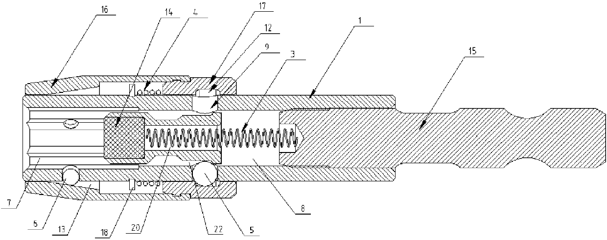
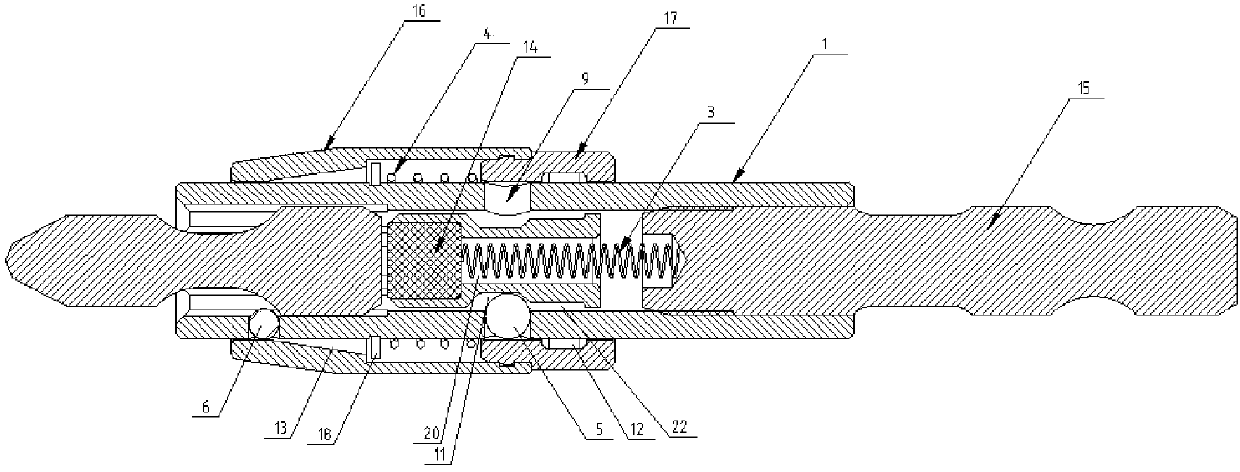
[0018] Embodiment: A magnetic automatic quick-lock chuck, including a mandrel, an outer sleeve, a sliding pin 2, a first elastic member 3, a second elastic member 4, a first slider 5 and a second slider 6, the mandrel One end is formed with a prism hole 7 for inserting the bit of a screwdriver, the bottom of the prism hole 7 is connected with a blind hole 8, and the side wall of the blind hole 8 of the mandrel is provided with at least two first radial perforations extending radially along the mandrel 9. There are at least two second radial perforations 10 extending radially along the mandrel axis on the side wall of the prism hole 7, and the first slider 5 can slide axially along the first radial perforations 9 and be positioned in the first radial perforations. 9, the second slider 6 can be axially slid and positioned in the second radial perforation 10 along the second radial perforation 10, and the two ends of the first and second sliders can extend out of the first and sec...


PUM


Abstract

The invention discloses an automatic magnetic rapid locking chuck. At least two second radial penetrable holes are formed in a prism hole; at least two first radial penetrable holes are formed in theside wall of a blind hole; the prism hole and the blind hole are formed at one end of a central spindle and communicate with each other; first sliding blocks are slidingly located in the first radialpenetrable holes; second sliding blocks are slidingly located in the second radial penetrable holes; the two ends of the first sliding blocks can stretch out of the first radial penetrable holes without dropping out; the two ends of the second sliding blocks can stretch out of the second radial penetrable holes without dropping out; a magnetic sliding pin can slide by the set distance in the axialdirection so as to be inserted into the blind hole of the central spindle; a first elastic piece provides the sliding pin with elastic force enabling the sliding pin to slide into the prism hole; oneends of the first sliding blocks can stretch into first radial indented groove structures on the side wall of the sliding pin; second radial indented groove structures and third radial indented groove structures are arranged on the inner side wall of an outer sleeve slidingly sleeving the outer side of the central spindle; one ends, facing the outer side of the central spindle, of the first sliding blocks can stretch into the second radial indented groove structures; one ends, facing the outer side of the central spindle, of the second sliding blocks can stretch into the third radial indentedgroove structures; and a second elastic piece provides the outer sleeve with elastic force enabling the outer sleeve to slide in the axial direction of the central spindle to force the first slidingblocks to be separated from second radial grooves and the second sliding blocks to be separated from third radial grooves. A screwdriver head can automatically exit without falling off, and the use issafe.

Description

technical field [0001] The invention relates to the technical field of a quick-release chuck, in particular to a magnetic automatic quick-lock chuck. Background technique [0002] When the screwdriver head is used on electric tools, it is necessary to use a quick-release chuck to realize the installation and positioning of the screwdriver head. At present, the quick-release chuck uses the inner surface of the jacket to tighten the steel ball under the action of elastic force, so that the steel ball snaps into the circumference of the screwdriver head. The axial positioning of the screwdriver bit is realized in the arc-shaped groove on the outer wall. When the screwdriver bit is to be removed, pull the cover to slide and release the steel ball. The screwdriver bit needs to be pulled out by hand while pulling the cover, which brings inconvenience to the operation. , requires two-handed operation, which is not applicable in some special working occasions. There is also an elast...

Claims


Application Information

Patent Timeline
IPC IPC(8): B25B23/12
CPCB25B23/12
Inventor 黄国庆
Owner 昆山义成工具有限公司
Why Eureka
Try Eureka