
Energy-saving device with high-pressure liquid storage and supply function and low-pressure gas-liquid separation function

A technology of low-pressure gas-liquid separation and high-pressure liquid storage, applied in refrigeration and liquefaction, lighting and heating equipment, refrigeration components, etc. , The effect of preventing the liquid supply from being gassed

Pending Publication Date: 2018-03-06
江苏世林博尔制冷设备有限公司
View PDF0 Cites 0 Cited by
  • Summary
  • Abstract
  • Description
  • Claims
  • Application Information

AI Technical Summary

Problems solved by technology

[0003] In order to solve the problems of compressor liquid shock and low energy efficiency ratio in the prior art, the object of the present invention is to provide an economizer with complete gas-liquid separation and energy saving

Method used


Image

  • Energy-saving device with high-pressure liquid storage and supply function and low-pressure gas-liquid separation function
  • Energy-saving device with high-pressure liquid storage and supply function and low-pressure gas-liquid separation function

Examples


Embodiment Construction

[0011] The specific embodiment of the present invention is described in further detail below in conjunction with accompanying drawing:

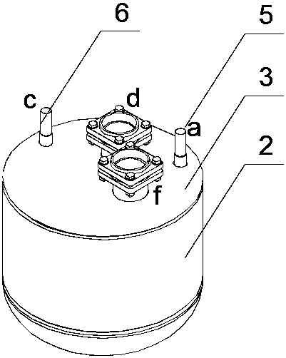
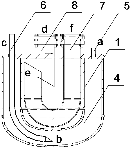
[0012] Such as Figure 1-2 As shown, an economizer with high-pressure liquid storage and liquid supply and low-pressure gas-liquid separation functions includes an inner cylinder 1 and an outer cylinder 2 coaxially arranged, the tops of the inner and outer cylinders are flush and sealed by a flat cover 3, and the inner and outer cylinders are sealed by a flat cover 3. The outer cylinder is composed of a cylinder section and a hemispherical head installed at the bottom of the cylinder section. The outer side of the inner cylinder and the inner side of the outer cylinder form a clamping cavity 4; the clamping cavity 4 is provided with a liquid inlet pipe 5 and a liquid outlet pipe 6. The top a protrudes from the flat cover 3 and is connected to the output end of the compressor, the bottom end of the inlet pipe slightly extends into the clamp ch...


PUM


Abstract

The invention relates to an energy-saving device with a high-pressure liquid storage and supply function and a low-pressure gas-liquid separation function. The energy-saving device comprises an innercylinder and an outer cylinder which are coaxially arranged, wherein the top of the inner cylinder and the top of the outer cylinder are flush and are sealed by a flat cover, and an interlayer cavityis formed between the outer side of the inner cylinder and the inner side of the outer cylinder; a liquid inlet pipe and a liquid outlet pipe are arranged in the interlayer cavity, the liquid inlet pipe is connected with the output end of a compressor, the bottom end of the liquid outlet pipe extends into the bottom of the interlay cavity, and the top end of the liquid outlet pipe extends out of the flat cover and is connected with the input end of an evaporator through a throttling valve; an air inlet pipe and an air outlet pipe are arranged in the inner cylinder, the air inlet pipe is a U-shaped pipe, one end of the air inlet pipe extends out of the flat cover and is connected with a liquid outlet of the evaporator, and the other end of the air inlet pipe extends to the top of the innercylinder; and the inlet of the air outlet pipe extends into the inner cylinder, the inlet of the air outlet pipe is lower than the outlet of the air inlet pipe, and the outlet of the air outlet pipe is connected with the output end of the compressor.

Description

technical field [0001] The invention belongs to the technical field of heat pump air conditioners, in particular to a new structure of an economizer. Background technique [0002] At present, the most common heat pump air-conditioning system is that the high-temperature and high-pressure gas-phase refrigerant discharged from the compressor passes through the condenser for heat exchange, and the refrigerant is converted from a gas phase to a liquid phase. After being condensed in the condenser, the refrigerant enters the high-pressure liquid receiver through a dry filter. The pure liquid-phase refrigerant discharged from the high-pressure liquid receiver passes through the economizer, increases the supercooling degree, and then enters the throttle valve. After passing through the isenthalpy throttling of the throttle valve, it lowers the temperature and pressure and enters the evaporator together with the gas-liquid two-phase flow ( The refrigerant (usually water) in the heat...

Claims


Application Information

Patent Timeline
IPC IPC(8): F25B43/00
CPCF25B43/00F25B43/006
Inventor 唐兴吴风雷
Owner 江苏世林博尔制冷设备有限公司
Features
  • Generate Ideas
  • Intellectual Property
  • Life Sciences
  • Materials
  • Tech Scout
  • Unparalleled Data Quality
  • Higher Quality Content
  • 60% Fewer Hallucinations
Learn More