Free-flying model jet test device

A test device and model technology, which is applied in the field of free-flying model jet test device, can solve the problems of air source installation, guidance, triggering, and free-flying model can not carry out active flow control, so as to prevent high-pressure gas leakage and good sealing Effect

Active Publication Date: 2019-05-24
CHINA ACAD OF AEROSPACE AERODYNAMICS
View PDF5 Cites 0 Cited by
  • Summary
  • Abstract
  • Description
  • Claims
  • Application Information

AI Technical Summary

Problems solved by technology

[0004] The technical problem to be solved by the present invention is: to overcome the deficiencies of the prior art, to provide a free-flying model air jet test device, which solves the shortcomings of the previous free-flying model that cannot carry out active flow control tests, and install the compressed air source on the model Internally, the problems of air source installation, guidance and triggering are overcome

Method used


Image

  • Free-flying model jet test device
  • Free-flying model jet test device
  • Free-flying model jet test device

Examples


Embodiment

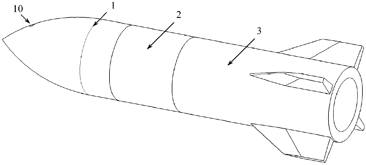
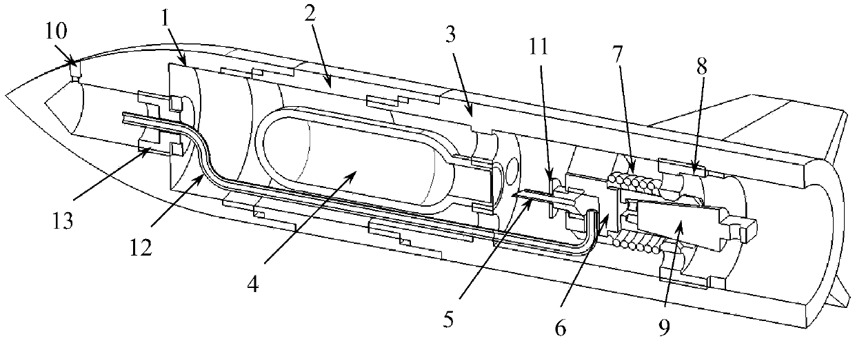
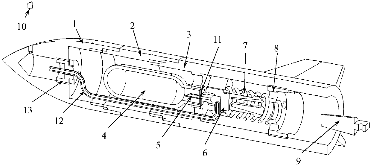
[0030] In this embodiment, the nozzle of the free-flying model jet test device is set on the model head 1 . The model head 1 is conical, the conical surface is an arc surface, the middle part 2 of the model, and the tail part 3 of the model are both cylindrical structures, and the tail part 3 of the model has an empennage at the end; The central axis is provided with a model head blind hole 1-2, and the side wall of the model head 1 is provided with a model head step hole 1-1, and the model head step hole 1-1 is connected with the blind end of the model head blind hole 1-2 , the spout modification block 10 is installed in the step hole 1-1 of the model head, the compressed gas cylinder 4 and the air injection mechanism are installed in the inner cavity of the model, and the compressed gas cylinder 4 is controlled by the air injection mechanism to generate gas, and the spout modification block 10 is in the gas Move to the outside of model head 1 under action. Guide tube fixing...


PUM


Abstract

The invention provides a free flight model jet test device comprising a model head part (1), a model intermediate section (2) and a model tail section (3). The model head part (1), the model intermediate section (2) and the model tail section (3) are connected in turn. The internal cavity of the model head part (1), the internal cavity of the model intermediate section (2) and the internal cavityof the model tail section (3) are communicated so as to form a model internal cavity. An internal cavity blind hole is arranged in the wall of the model internal cavity. A jet tip modification block (10) is installed on the external wall of any section of the model head part (1), the model intermediate section (2) and the model tail section (3). The installing hole of the jet tip modification block (10) is communicated with the internal cavity blind hole. A compressed gas cylinder (4) and a jet mechanism are installed in the model internal cavity. The compressed gas cylinder (4) is controlledto generate gas through the jet mechanism. The jet tip modification block (10) is jetted out under the effect of the gas. The disadvantages that the conventional free flight model cannot perform active flow control type test can be solved and the problems of gas source installation, guidance and triggering can be overcome.

Description

technical field [0001] The invention relates to a wind tunnel test model, in particular to an air jet test device for a free-flying model. Background technique [0002] Air jet control is a commonly used active flow control method. Usually, air jets are opened on the surface of the model that needs to improve the quality of the flow field, and the gas is injected to the outside of the aircraft as needed, thereby changing the flow field mechanism on the surface of the aircraft and providing additional air for the aircraft. Power and moment, in the field of aerospace, jet active control method is a hot research topic. Model free-flying wind tunnel test is a commonly used research method to study the dynamic aerodynamic characteristics of aircraft. It has the unique characteristic of unsupported interference, which is different from other steady and quasi-steady test methods. The basic method of the model free-flying wind tunnel test is to eject the model at high speed against...

Claims


Application Information

Patent Timeline
Patent Type & Authority Patents(China)
IPC IPC(8): G01M9/08
CPCG01M9/08
Inventor 薛飞王誉超杨益农蒋增辉
Owner CHINA ACAD OF AEROSPACE AERODYNAMICS
Why Eureka
Try Eureka