Continuous zoom contact lenses

A technology of contact lenses and light mirrors, applied in the field of glasses, can solve problems such as decreased visual contrast, image skipping, dizziness or maladaptation of the wearer, and achieve the effects of correcting ametropia and relieving stress

Active Publication Date: 2021-04-02
九扬贸易有限公司
View PDF2 Cites 0 Cited by
  • Summary
  • Abstract
  • Description
  • Claims
  • Application Information

AI Technical Summary

Problems solved by technology

However, the biggest problem with the multifocal contact lens 7 is that when the wearer looks at the different focus areas 71 and 72 of the multifocal contact lens 7 when looking at the far and near, in order to achieve the instant conversion of seeing near and far, the different focal points The dioptric power between the regions 71 and 72 fluctuates rapidly. Some wearers' eyes 9 cannot adapt to the above-mentioned sudden diopter power change, which will cause image skipping and blurring. After long-term wear, the wearer is prone to adverse reactions such as dizziness or maladaptation

Method used


Image

  • Continuous zoom contact lenses
  • Continuous zoom contact lenses
  • Continuous zoom contact lenses

Examples


Embodiment 1

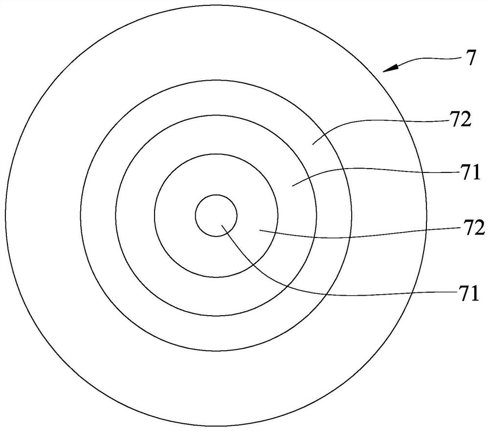
[0044] refer to Figure 5 , Image 6 and Figure 7 , the continuous zoom contact lens 1 of Example 1 of the present invention is suitable for the design of a stress-relieving lens that relieves the burden of eyes 9 watching at close range. The central optical axis L of the continuous zoom contact lens 1 is the center of a circle and is surrounded by a first optical zone 111, a second optical zone 112, and a peripheral zone 12 with radii of 1.5mm, 3mm, and 7.1mm respectively. . The second optical zone 112 extends outward from the outer edge of the first optical zone 111 , and the peripheral zone 12 extends outward from the outer edge of the second optical zone 112 . The thickness of the central optical axis L of the continuous zoom contact lens 1 is 0.08mm, the base arc radius of curvature of the first optical zone 111 is 8.6mm and the conic constant (K) is 0.3, the starting point of the first optical zone 111 The initial diopter power is -3.0D, the average change rate of t...

Embodiment 2

[0048] refer to Figure 5 , Image 6 and Figure 8 , Embodiment 2 of the present invention is suitable for slowing down children's myopia, which is substantially the same as Embodiment 1, except that the continuous zoom contact lens 1 is formed by polymerization and compression molding of silicon hydrogel (Silicon hydrogel) by UV light irradiation, and the first An optical zone 111, the second optical zone 112 and the peripheral zone 12 take the central optical axis L as the center and are respectively surrounded and defined by radii of 1.0mm, 3.0mm and 7.0mm. The base arc of the first optical zone 111 The radius of curvature is 8.5mm and the conic constant (K) is 0.8, the initial diopter power of the first optical zone 111 is -3.0D, and the average change rate of the diopter power of the first optical zone 111 outward along the radial direction is + 0.125D / mm, the average change rate of the dioptric power of the second optical zone 112 outward along the radial direction is ...

Embodiment 3

[0051] refer to Figure 5 , Image 6 and Figure 9 , embodiment 3 of the present invention is suitable for the continuous zoom contact lens 1 of presbyopia patient, and it is roughly the same as this embodiment 1, and difference is: this continuous zoom contact lens 1 is molded with water gel (Hygrogel) by UV light irradiation polymerization , the first optical zone 111, the second optical zone 112 and the peripheral zone 12 take the central optical axis L as the center and are respectively surrounded and defined by radii of 1.0 mm, 3.0 mm and 7.0 mm. The first optical zone 111 The initial diopter power of the first optical zone 111 is zero, the average change rate of the diopter power of the first optical zone 111 radially outward is +0.25D / mm, and the average change rate of the dioptric power of the second optical zone 112 radially outward The refractive power of the second optical zone 112 to the edge with a radius of 3mm is +2.5D.

[0052]The continuous zoom contact len...


PUM


Abstract

The invention relates to a continuous zooming contact lens, which comprises a central optical zone and a peripheral zone, wherein the central optic zone comprises a first optic zone and a second opticzone, the first optical zone is a circular zone enclosed by using one central optical axis of the continuous zooming contact lens as the circle center and has a radius of 1.5+ / -1.0 mm, the second optic zone extends radially and outwardly from the peripheral edge of the first optic zone to the peripheral zone, the diopter of the continuous zooming contact lens is radially and continuously changed,and the average change rate of the diopter is less than 0.25 D / mm in the first optical zone and is more than 0.25 D / mm in the second optical zone. According to the present invention, by radially andcontinuously changing the diopter, the continuous zooming contact lens can correct the refractive error of eyeball and simultaneously correct the imaging focal point around retina, such that the smooth and image-jump-free myopia defocus around retina can be generated.

Description

technical field [0001] The invention relates to glasses, in particular to a contact lens. Background technique [0002] refer to figure 1 , the eyes 9 of the myopia patient image the distant scene in front of the retina 91, so a clear image cannot be formed on the retina 91. However, see figure 2 When the myopic patient's eye 9 wears a myopic contact lens 8 with a concave lens, the distant scene is imaged on the retina 91 through the correction and adjustment of the myopic contact lens 8 . [0003] When the above-mentioned myopia patients confirm the degree of myopia and make glasses, they take long-distance measurement to find out the myopia contact lens 8 that can correct the eyesight of the myopia patient. The final visual acuity is 1.0 sharpness, and you can see clearly the scenery five meters away. [0004] However, myopia patients mostly wear the above-mentioned myopic contact lenses 8 configured for long-distance measurement, watch the screens of electronic produ...

Claims


Application Information

Patent Timeline
Patent Type & Authority Patents(China)
IPC IPC(8): G02C7/04
CPCG02C7/041
Inventor 王宗林
Owner 九扬贸易有限公司
Why Eureka
Try Eureka