
Spot light source matching method and device in eye-tracking device

A technology of eye tracking and matching method, which can be used in image analysis, instrumentation, calculation and other directions, and can solve problems such as difficulty in matching light source

Active Publication Date: 2020-03-27
BEIJING 7INVENSUN TECH
View PDF7 Cites 0 Cited by
  • Summary
  • Abstract
  • Description
  • Claims
  • Application Information

AI Technical Summary

Problems solved by technology

[0004] Embodiments of the present invention provide a method and device for matching light spots and light sources in eye-tracking equipment, so as to at least solve the technical problem of difficulty in matching light spots and light sources in the use of eye-tracking equipment in the prior art

Method used


Image

  • Spot light source matching method and device in eye-tracking device
  • Spot light source matching method and device in eye-tracking device
  • Spot light source matching method and device in eye-tracking device

Examples


Embodiment 1

[0024] According to an embodiment of the present invention, a method embodiment of a spot light source matching method in a gaze tracking device is provided. It should be noted that the steps shown in the flow chart of the accompanying drawings can be implemented in a computer system such as a set of computer-executable instructions and, although a logical order is shown in the flowcharts, in some cases the steps shown or described may be performed in an order different from that shown or described herein.

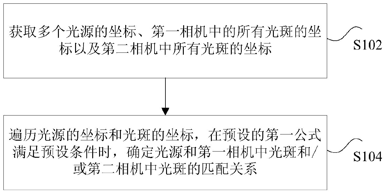
[0025] figure 1 is a method for matching light spots and light sources in a gaze tracking device according to an embodiment of the present invention, wherein the gaze tracking device includes a first camera and a second camera, such as figure 1 As shown, the method includes the following steps:

[0026]Step S102, obtaining coordinates of multiple light sources, coordinates of all light spots in the first camera, and coordinates of all light spots in the second camera, whe...

Embodiment 2

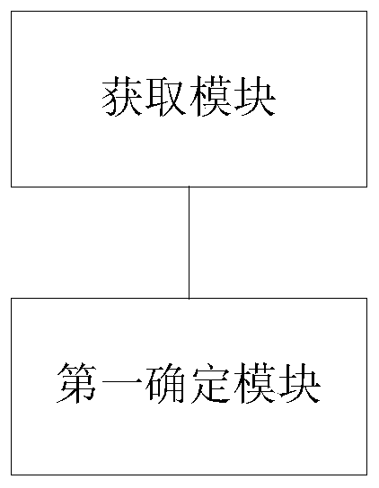
[0054] According to an embodiment of the present invention, a product embodiment of a spot light source matching device in a gaze tracking device is provided, image 3 is a spot light source matching device in a gaze tracking device according to an embodiment of the present invention, wherein the gaze tracking device includes a first camera and a second camera, such as image 3 As shown, the device includes an acquisition module and a first determination module, wherein the acquisition module is used to acquire the coordinates of multiple light sources, the coordinates of all light spots in the first camera, and the coordinates of all light spots in the second camera, wherein the multiple A light source is reflected by the cornea and projected on the first camera and the second camera to obtain a light spot; the first determination module is used to traverse the coordinates of the light source and the coordinates of the light spot, and determine the light source when the preset...

Embodiment 3

[0065] According to an embodiment of the present invention, a product embodiment of a storage medium is provided. The storage medium includes a stored program, wherein when the program is running, the device where the storage medium is located is controlled to execute the above method for matching light spots and light sources in the gaze tracking device.


PUM


Abstract

The invention discloses a light spot-light source matching method and device in a sight line tracking device. The sight line tracking device is composed of a first camera and a second camera. The method comprises: coordinates of a plurality of light sources, coordinates of all light spots in the first camera and coordinates of all light spots in the second camera are obtained, wherein the multiplelight sources are reflected by a cornea and then projection is carried out at the first camera and the second camera to obtain light spots; and traverse processing is carried out on the coordinates of the light sources and the coordinates of the light spots, and a matching relationship between the light sources and the light sources in the first camera and / or between the light sources and the light sources in the second camera are / is determined. Therefore, a technical problem of difficult light spot-light source matching in application of teh sight line tracking device in the prior art is solved.

Description

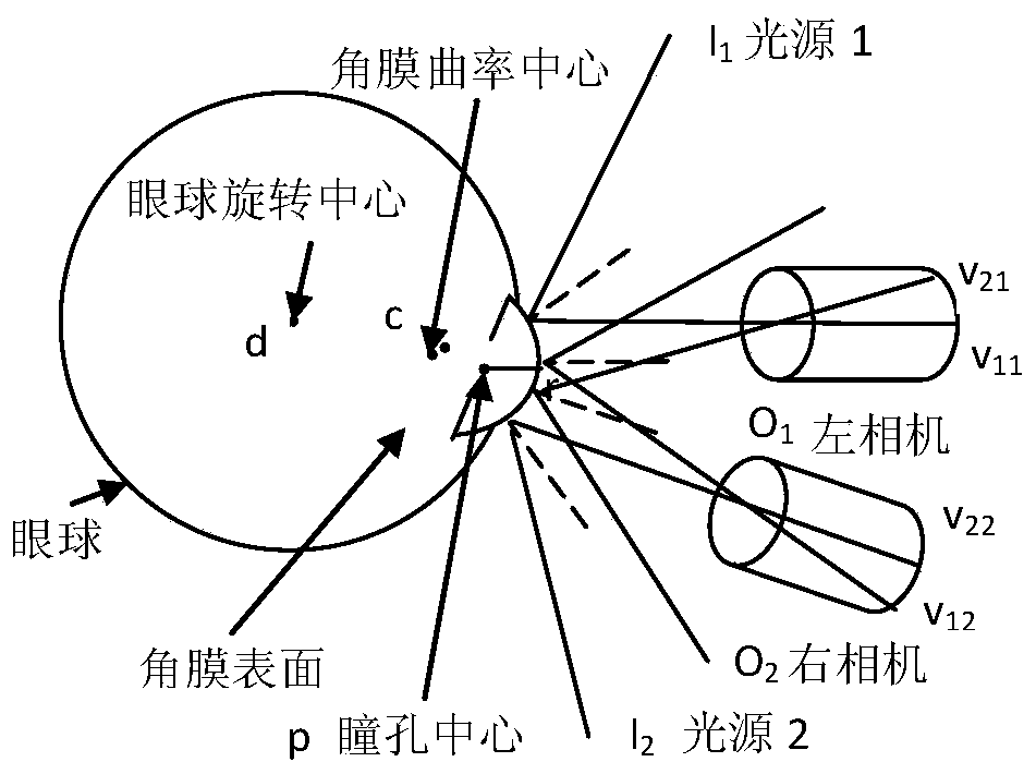
technical field [0001] The present invention relates to the field of eye-tracking equipment, in particular to a method and device for matching light spots and light sources in eye-tracking equipment. Background technique [0002] In the prior art, when using a gaze tracking device, based on the 3D approximate spherical model of the eyeball, the VR device estimates the line of sight of the long-distance device at the gaze point based on the pupil center coordinates and corneal reflection. When the VR device uses multiple cameras and multiple light sources , the line of sight can be estimated only by a single-point correction process. In actual use of the above-mentioned VR equipment, because the relative positions of the light source and the camera are different, the camera cannot capture the image at some positions, or the captured image is not good. In this case In this case, because the light source is often not specific, the matching of the light source spot cannot be com...

Claims


Application Information

Patent Timeline
Patent Type & Authority Patents(China)
IPC IPC(8): G06T7/80
Inventor 刘伟聂凤梅宫小虎任冬淳杨孟
Owner BEIJING 7INVENSUN TECH
Learn More