
Buoyancy demonstration device for physics teaching

A demonstration device and buoyancy technology, applied in the field of buoyancy demonstration devices for physics teaching, can solve the problems of fluid loss, time-consuming and labor-intensive problems

Active Publication Date: 2020-04-07
合浦县石康中学
View PDF4 Cites 0 Cited by
  • Summary
  • Abstract
  • Description
  • Claims
  • Application Information

AI Technical Summary

Problems solved by technology

[0004] However, in the existing buoyancy demonstration device, teachers or students need to manually adjust the weight of the float during the demonstration. When adjusting the density of the fluid, it is necessary to use a stirring rod or a stirring device, etc., resulting in fluid loss. It is also necessary to clean the stirring rod or Stirring device, etc., time-consuming and labor-intensive

Method used


Image

  • Buoyancy demonstration device for physics teaching
  • Buoyancy demonstration device for physics teaching
  • Buoyancy demonstration device for physics teaching

Examples


Embodiment Construction

[0032] The present invention will be further described in detail below in conjunction with the accompanying drawings, so that those skilled in the art can implement it with reference to the description.

[0033] It should be noted that, in the description of the present invention, the terms "horizontal", "vertical", "upper", "lower", "front", "rear", "left", "right", "vertical", The orientation or positional relationship indicated by "horizontal", "top", "bottom", "inner", "outer", etc. is based on the orientation or positional relationship shown in the drawings, and is only for the convenience of describing the present invention and simplifying the description, and It is not to indicate or imply that the device or element referred to must have a particular orientation, be constructed in a particular orientation, or operate in a particular orientation, and thus should not be construed as limiting the invention.

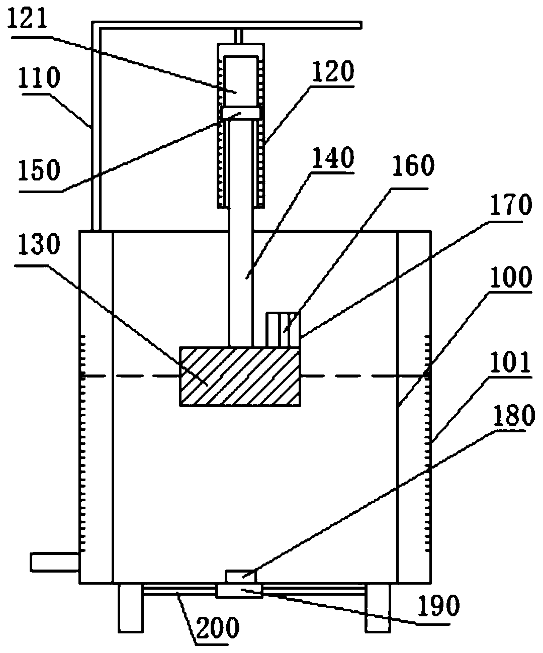
[0034] like Figure 1 to Figure 4 As shown, the present inventi...


PUM


Abstract

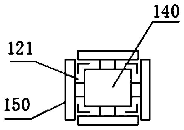
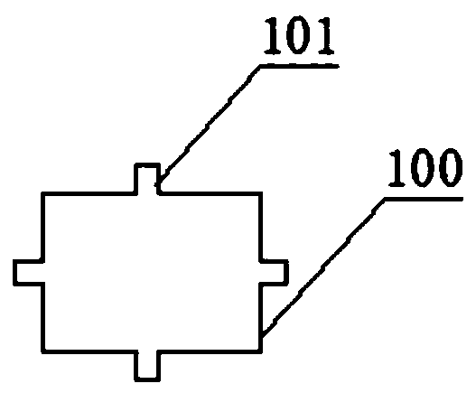
The invention discloses a floatage demonstration device for physics teaching, and belongs to the technical field of physical experiment instruments. The floatage demonstration device comprises a tank,a support frame, a cubic measuring drum, a floating drum, a connecting rod and four inverted-T-shaped indicating blocks. A squire opening is formed in each of four side walls of the measuring drum. The top of the measuring drum is connected with the top of the support frame fixedly. The floating drum is located in the tank. The top of the connecting rod is inserted into the measuring drum. The four indicating blocks correspond to the openings one by one. One indicating block corresponds to one side wall of the connecting rod. The inverted-T-shaped portion of each indicating block penetrates the corresponding opening to be fixedly connected with the corresponding side wall of the connecting rod. The other portion of each indicating block is located in the corresponding opening or outside the measuring drum. The floatage demonstration device has the advantages that the weight of the floating drum can be changed through an electromagnetic coil; a first magnet and a second magnet are arranged at the bottom of the tank, the second magnet drives the first magnet to move, and fluids in the tank can be stirred, so that density of the fluids is changed; the floatage demonstration device issimple to operate and has high efficiency.

Description

technical field [0001] The invention relates to the technical field of physical experiment instruments. More specifically, the present invention relates to a buoyancy demonstration device for physics teaching. Background technique [0002] Buoyancy refers to the difference (combined force) between the pressure of the fluid (liquid and gas) on each surface of an object in a fluid (including liquid and gas). Archimedes' law is an important principle of hydrostatics. It points out that an object immersed in a static fluid is subjected to a buoyant force equal to the weight of the fluid displaced by the object, and the direction is vertically upward and passes through the shape of the displaced fluid. Heart. [0003] In middle school physics course teaching, the understanding of the cause of buoyancy, the influencing factors of buoyancy, and Archimedes' law is the focus and difficulty of physics course. Therefore, when teachers explain, they generally use buoyancy experiments...

Claims


Application Information

Patent Timeline
Patent Type & Authority Patents(China)
IPC IPC(8): G09B23/12
CPCG09B23/12
Inventor 孙锡洪
Owner 合浦县石康中学
Learn More