Humidity relay protector used for power transformation box

A technology of relay protectors and relay protection devices, applied in circuits, electric switches, electrical components, etc., which can solve problems such as frequent maintenance, easy heating of springs, and increased workload, so as to reduce the number of maintenance and workload , convenient fastening effect

Inactive Publication Date: 2018-03-06
乐见协
View PDF5 Cites 3 Cited by
  • Summary
  • Abstract
  • Description
  • Claims
  • Application Information

AI Technical Summary

Problems solved by technology

[0005] Aiming at the deficiencies in the prior art, the purpose of the present invention is to provide a humidity relay protector used in a transformer box to solve the problem that the existing relay protector generally uses a spring for reset, but the spring is easy to generate heat and needs to be checked frequently Whether there is deformation, frequent maintenance, increased workload

Method used


Image

  • Humidity relay protector used for power transformation box
  • Humidity relay protector used for power transformation box
  • Humidity relay protector used for power transformation box

Examples


Embodiment Construction

[0025] In order to make the technical means, creative features, goals and effects achieved by the present invention easy to understand, the present invention will be further described below in conjunction with specific embodiments.

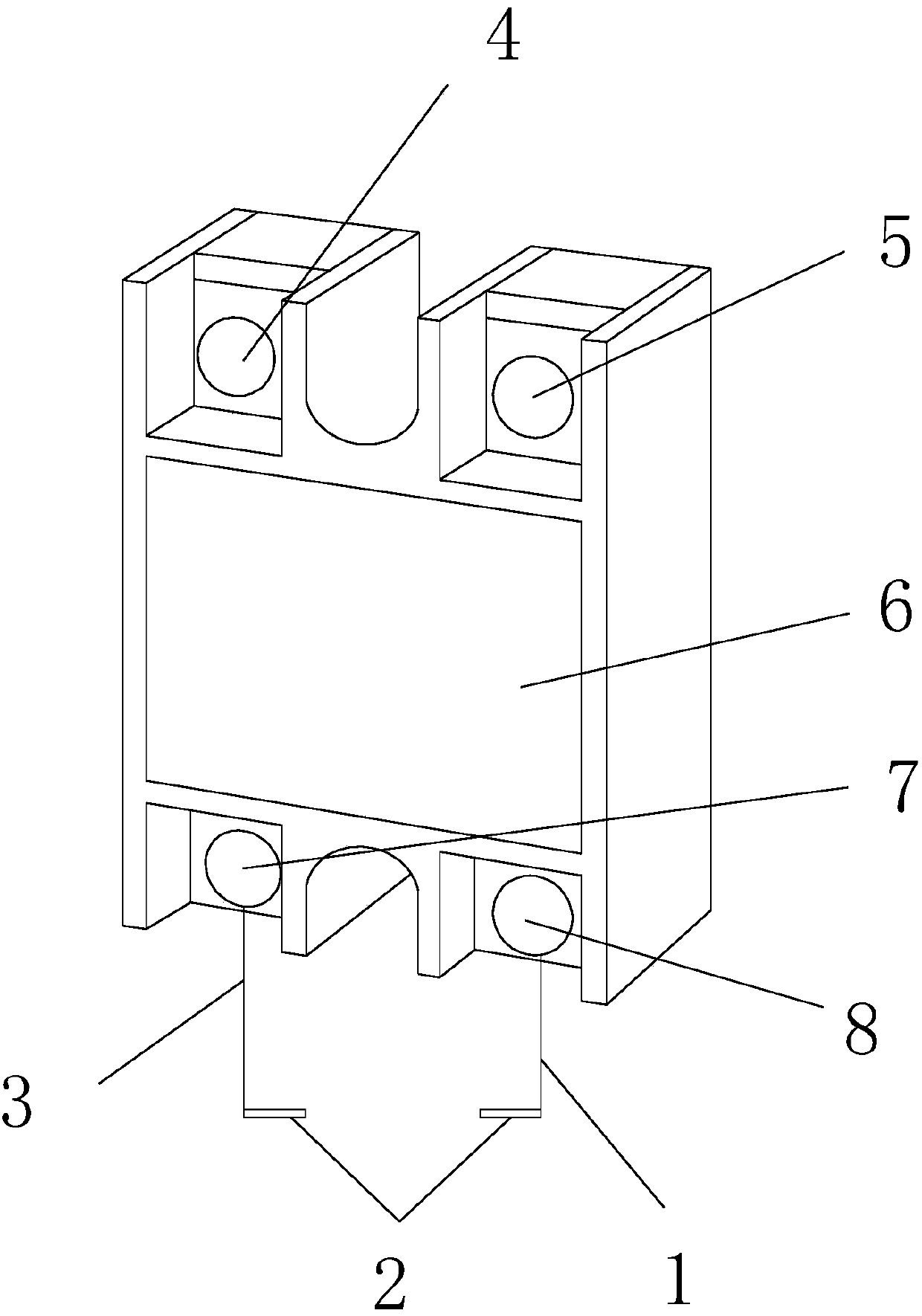
[0026] see Figure 1-Figure 6 , the present invention provides a technical solution for a humidity relay protector for a transformer box: its structure includes a first lead 1, a metal pin 2, a second lead 3, a power connector 4, a load connector 5, and a relay protection device 6. Low-voltage power supply positive connector 7, low-voltage power supply negative connector 8, the relay protection device 6 is provided with power connector 4, load connector 5, low-voltage power supply positive connector 7, low-voltage power supply negative connector 8, the metal pin 2 There are two, the positive terminal 7 of the low-voltage power supply is connected to one of the metal pins 2 through the second lead 3, and the negative terminal 8 of the low-voltage p...


PUM


Abstract

The invention discloses a humidity relay protector used in a transformer box. The humidity relay protector used in a transformer box comprises a first lead, a metal pin, a second lead, a power connector, Load connectors, relay protection devices, low-voltage power supply positive connectors, low-voltage power supply negative connectors, the relay protection device is equipped with power connectors, load connectors, low-voltage power supply positive connectors, low-voltage power supply negative connectors, and metal pins. The positive connector is connected to one of the metal pins through the second lead, and the negative connector of the low-voltage power supply is connected to the remaining metal pins through the first lead. , will not be deformed, does not need frequent maintenance, reduces the number of maintenance, and reduces the workload.

Description

technical field [0001] The invention relates to a humidity relay protector used in a transformer box, which belongs to the field of power distribution. Background technique [0002] Relay (English name: relay) is an electrical control device, which is an electrical appliance that causes the controlled quantity to undergo a predetermined step change in the electrical output circuit when the change of the input quantity (excitation quantity) meets the specified requirements. It has an interactive relationship between the control system (also known as the input loop) and the controlled system (also known as the output loop). Usually used in automatic control circuits, it is actually an "automatic switch" that uses a small current to control the operation of a large current. Therefore, it plays the role of automatic adjustment, safety protection, and conversion circuit in the circuit. [0003] The substation box is already an indispensable equipment in daily life. It is often ...

Claims


Application Information

Patent Timeline
Patent Type & Authority Applications(China)
IPC IPC(8): H01H35/42
CPCH01H35/42
Inventor 乐见协周博滔陈寨辉
Owner 乐见协
Why Eureka
Try Eureka