
Embedded ceramic cavity filter

A cavity filter and embedded technology, applied in the field of filters, can solve the problems of poor low-frequency band suppression, power only 1-30W, heavy weight, etc., to improve mutual interference between signals and large loss, improve poor suppression, The effect of improving performance

Inactive Publication Date: 2018-03-06
SUZHOU RF TOP ELECTRONICS COMM +2
View PDF14 Cites 3 Cited by
  • Summary
  • Abstract
  • Description
  • Claims
  • Application Information

AI Technical Summary

Problems solved by technology

[0002] Ceramic dielectric filters are mainly used in microwave communication systems. It can effectively obtain the required frequency range, but its disadvantages are poor suppression in the low frequency band, large loss, and its power is only 1 to 30W
In addition, the cavity filter currently used in the base station has the advantages of high power and high rejection, but the cavity filter itself has the disadvantages of large size, heavy weight and difficult fabrication

Method used


Image

  • Embedded ceramic cavity filter
  • Embedded ceramic cavity filter
  • Embedded ceramic cavity filter

Examples


Embodiment Construction

[0020] In order to make the object, technical solution and advantages of the present invention clearer, the present invention will be further described in detail below in conjunction with the accompanying drawings and embodiments. It should be understood that the specific embodiments described here are only used to explain the present invention, not to limit the present invention.

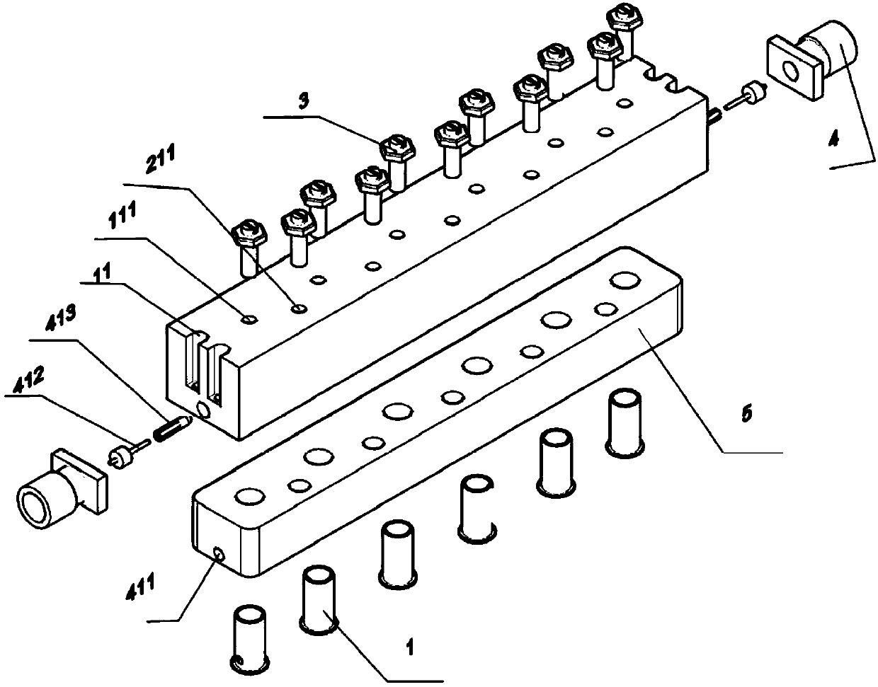
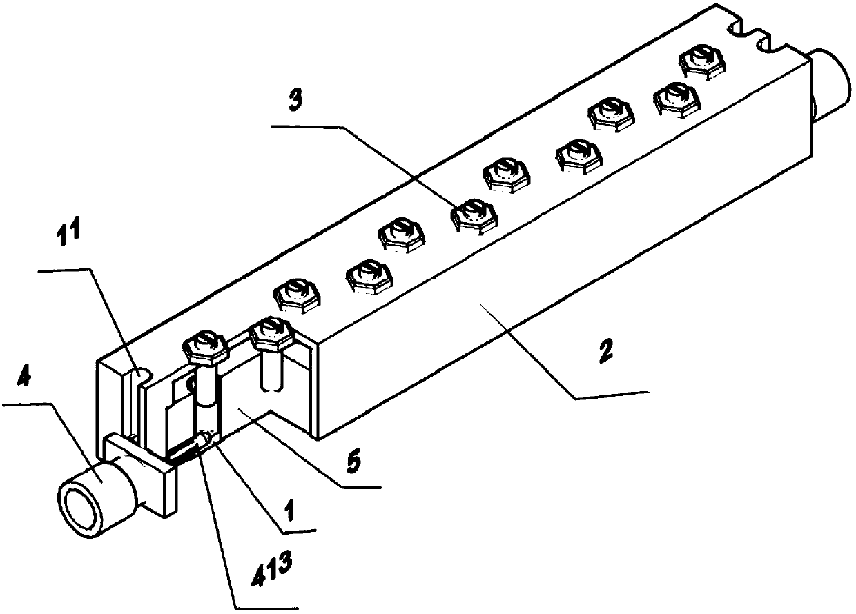
[0021] The invention relates to mobile communication base station equipment, a high-frequency filter for filtering required frequencies through unnecessary frequencies in high-frequency communication equipment, especially compared with existing cavity filters, which are relatively miniaturized, light in weight, and relatively smaller than ceramics The dielectric filter has low loss and high suppression, and its advantages are summarized as a ceramic cavity filter suitable for high-power base station equipment and high-frequency communication equipment. Please also refer to figure 1 , figure 2 , ...


PUM


Abstract

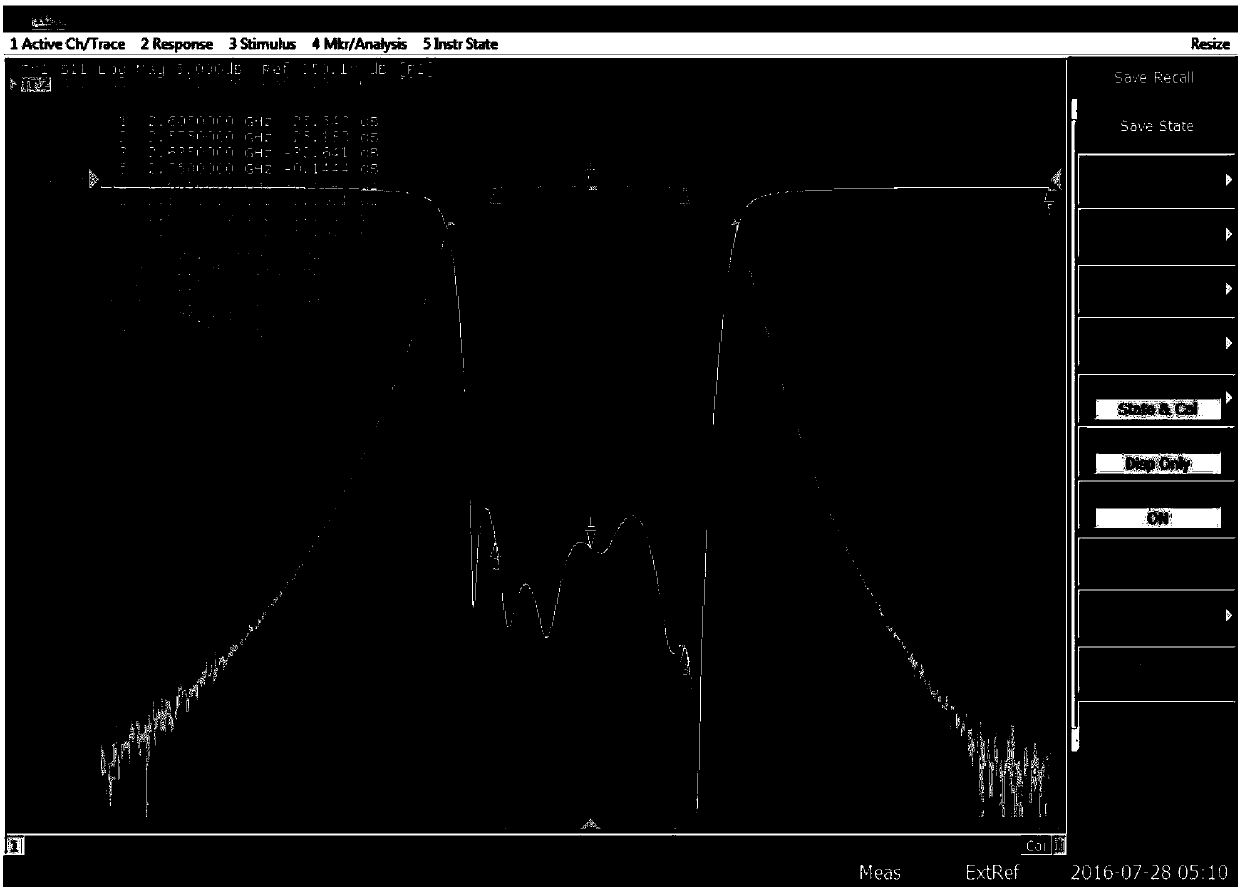
The invention discloses an embedded ceramic cavity filter comprising n resonators, a ceramic block and a metal cavity, wherein n is not less than 2. The resonator is accommodated in the metal cavity by being embedded in the ceramic block; the filter is provided with n resonance holes and n-1 coupling holes. Each resonator hole penetrates the ceramic block from the top surface of the metal cavity and extends into the corresponding resonator; each coupling hole extends into the ceramic block from the top surface of the metal cavity and is located between two adjacent resonators. The invention can adjust the frequency and has a closed cavity structure to be embodied by using a resonator, so as to improve the problem that the conventional ceramic filter cannot achieve the suppression difference, mutual interference between signals, and large loss. The invention uses the form of resonator insertion to minimize the loss and improve the performance, and the Qu value is 1.5 to 2 times higher than the ceramic filter; at the same time, the cavity filter has the features of miniaturization and light weight.

Description

technical field [0001] The invention relates to a filter, in particular to an embedded ceramic cavity filter. Background technique [0002] Ceramic dielectric filters are mainly used in microwave communication systems. It can effectively obtain the required frequency range, but its disadvantages are poor suppression in low frequency bands, large losses, and its power is only 1 to 30W. In addition, the current cavity filter used in the base station has the advantages of high power and high rejection, but the cavity filter itself has the disadvantages of large volume, heavy weight and difficult fabrication. Contents of the invention [0003] In order to solve the defects in the background technology, the present invention provides an embedded ceramic cavity filter. [0004] The solution of the present invention is: an embedded ceramic cavity filter, which includes n resonators, a ceramic block, and a metal cavity; n is not less than 2; the resonator is accommodated in the m...

Claims


Application Information

Patent Timeline
Patent Type & Authority Applications(China)
IPC IPC(8): H01P1/208
CPCH01P1/208H01P1/2084H01P1/2138H01P7/10
Inventor 陈荣达金壽善
Owner SUZHOU RF TOP ELECTRONICS COMM
Learn More