Wire clamping device

A wire clamp and shrapnel technology, which is applied in the field of wire clamps, can solve problems such as damage to the wire end and inability to achieve protection effects, and achieve the effects of convenient wire management, good protection effect, and not easy to damage.

Inactive Publication Date: 2018-03-06
MIANYANG XINYANG INTPROP CO LTD
View PDF3 Cites 0 Cited by
  • Summary
  • Abstract
  • Description
  • Claims
  • Application Information

AI Technical Summary

Problems solved by technology

The existing device for clamping wires is easy to damage the wire ends during the process of clamping the terminal and in the later use process, and cannot achieve a good protection effect

Method used


Image

  • Wire clamping device

Examples


Embodiment 1

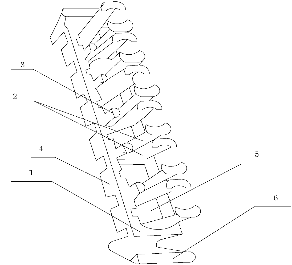
[0019] Such as figure 1 As shown, the present invention includes a wire clamp, including a base 1, a plurality of main shrapnel 2, a plurality of auxiliary shrapnel 3, and a jack 5. The base 1 is evenly provided with a plurality of jacks 5, and each jack 5 is evenly A pair of main shrapnel 2 and a secondary shrapnel 3 are provided. The pair of main shrapnels 2 are symmetrical and parallel to each other about the axis of symmetry. The sub shrapnel 3 is installed on the base 1 between the pair of main shrapnel 2 on each socket 5, The height of the shrapnel 3 is 1 / 2 of the height of the main shrapnel 2, and a convex protective cover 4 is also provided at the bottom of each socket 5.

[0020] When in use, insert the connector into the jack. A pair of main shrapnel and a secondary shrapnel are used to enclose an area to protect the connection end of the connector. The convex protective cover located at the lower part of the jack plugs the entire connector. The terminal protection is ...

Embodiment 2

[0022] This embodiment is preferably as follows on the basis of the first embodiment: the base 1 is also provided with protective plates 6 at both ends, and the shape of the protective plates 6 is V-shaped. It is used to isolate the obstacles on both sides to avoid damage to the terminals located in the sockets at both ends.

[0023] The top of each main shrapnel 2 has a semicircular structure, and a pair of main shrapnel 2 on the socket 5 forms a circular area. Semi-circular structure, no sharp edges and corners, in the process of plugging the terminal, the terminal is safer.

[0024] The height of each main shrapnel 2 ranges between 5-10 cm. This height can better protect the terminal of the terminal without affecting the observation of the terminal.

[0025] The base 1, the main shrapnel 2 and the auxiliary shrapnel 3 are all elastic. Since the terminal needs to pass through the base during the process of inserting it into the jack, and the base is also set to be flexible, the ...


PUM


Abstract

The invention discloses a wire clamping device. The wire clamping device comprises a base, a plurality of main elastic sheets, a plurality of secondary elastic sheets and inserting holes; multiple inserting holes are uniformly formed in the base; a pair of main elastic sheets and a pair of secondary elastic sheets are arranged on each inserting hole; one pair of main elastic sheets are symmetricalaround a symmetrical shaft and are in parallel mutually; the corresponding secondary elastic sheets are mounted on the base between the pair of main elastic sheets on each inserting hole; the heightof the secondary elastic sheets is 1 / 2 of that of the main elastic sheets; and an outwardly convex protection cover is arranged at the bottom of each inserting hole. By adoption of the structure, thewire clamping device can provide all-around protection for a wire connector, so that the wire connector is not damaged easily.

Description

Technical field [0001] The present invention relates to the field of communication, in particular to a wire card device. Background technique [0002] Since human beings existed, they have always had to exchange ideas and transmit information. Humans in ancient times used facial expressions and movements to communicate information, which was the most primitive way of communication. Later, human beings created language and writing in their long lives. Mankind has also created many methods of information transmission, such as ancient beacon towers, golden drums, pennants, and signal lights for navigation. These are all ways to solve long-distance information transmission. After entering the 19th century, people began to try to communicate using electrical signals. Cable communication is the earliest communication technology developed. It has been used for long-distance communication for more than 60 years and has a prominent position in communication. In the process of cable co...

Claims


Application Information

Patent Timeline
Patent Type & Authority Applications(China)
IPC IPC(8): H02G1/00H02G1/02
CPCH02G1/00H02G1/02
Inventor 龚平
Owner MIANYANG XINYANG INTPROP CO LTD
Why Eureka
Try Eureka