Water floating photovoltaic array

A photovoltaic array and floating body technology, applied in photovoltaic power generation, photovoltaic modules, photovoltaic module support structures, etc., can solve the problems of high failure rate of tracking technology, low sunlight utilization efficiency, and high cost of photovoltaic power generation, so as to improve the utilization rate of sunlight and Reliability, reduction of power generation costs, and material saving effects

Inactive Publication Date: 2018-03-06
曹欣峰
View PDF0 Cites 4 Cited by
  • Summary
  • Abstract
  • Description
  • Claims
  • Application Information

AI Technical Summary

Problems solved by technology

[0003] The purpose of the present invention is to solve the problems of high photovoltaic power generation cost, low sunlight utilization efficiency, and high failure rate of existing tracking technology in the existing fixed water platform; improve sunlight utilization and reliability, save materials, and improve economic benefits

Method used


Image

  • Water floating photovoltaic array

Examples


specific Embodiment approach 1

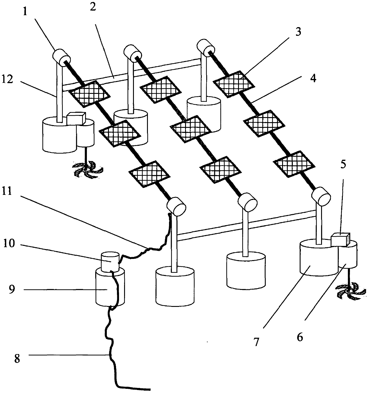
[0009] As shown in the figure, a floating photovoltaic array on water, the floating photovoltaic array on water includes a rotation controller 1, a connecting rod 2, a solar panel 3, a beam 4, a positioning controller 5, a propeller 6, a floating body 7, a support Column 12, solar panel 3 is fixed on beam 4, solar panel 3 on each beam 4 has equal intervals and the same inclination angle, connecting rod 2 is connected with support column 12, and rotation controller 1 is connected with beam 4, and rotation controller 1 is connected to the support column 12, the support column 12 is connected to the floating body 7, the positioning controller 5 is connected to the propeller 6, and the propeller 6 is connected to the floating body 7. The positioning controller 5 controls the propeller 6 to rotate according to remote control instructions or satellite positioning signals, thereby pushing the photovoltaic array to move, so that the photovoltaic array is in a designated position and th...

specific Embodiment approach 2

[0011] As shown in the figure, the floating photovoltaic array also includes a power transmission cable 8, a cable floating body 9, a confluence 10, and a confluence cable 11. One end of the confluence cable 11 is connected to the rotation controller 1, and the other end of the confluence cable 11 is connected to the confluence 10. , the cable floating body 9 is connected to the confluence 10 , and the confluence 10 is connected to the transmission cable 8 . The power transmission cable 8 can transmit the electric energy emitted by the floating photovoltaic array to nearby islands or land.


PUM


Abstract

The invention discloses a water floating photovoltaic array, which comprises rotating controllers, connecting rods, solar cell panels, beams, positioning controllers, propellers, floating bodies andsupport columns, wherein the solar cell panels are fixed on the corresponding beams; the solar cell panels on each beam have the same intervals and dip angles; the connecting rods are connected with the corresponding support columns; eaah rotating controller is connected with the corresponding beam and connected with the corresponding support column; each support column is connected with the corresponding floating body; each positioning controller is connected with the corresponding propeller; and each propeller is connected with one floating body. Multiple groups of water floating photovoltaic arrays can be adopted to form one larger water floating photovoltaic array. The bottleneck of restricting promotion and use of solar photovoltaic power generation is broken through, the generating cost of solar photovoltaic power generation is significantly reduced and the economic benefit is improved.

Description

technical field [0001] The invention relates to the technical field of photovoltaic power generation, in particular to a floating photovoltaic array on water. Background technique [0002] Solar power generation is increasingly valued by countries all over the world. China is relatively rich in solar energy resources, and the development potential of solar photovoltaic power generation is huge. However, solar power generation needs to occupy a huge area. Today, as land resources become increasingly tense, people begin to consider water photovoltaic power generation. Vast lakes, oceans, and rivers can all become solar power plants, which can effectively solve the bottleneck problem of solar power generation sites. Most of the current floating solar power generation technologies use fixed floating platforms. The solar panels in the photovoltaic array are closely arranged in a fixed position like power generation on land. In the prior art, individual battery boards are used t...

Claims


Application Information

Patent Timeline
Patent Type & Authority Applications(China)
IPC IPC(8): H02S20/32B63B35/44
CPCB63B35/44H02S20/32Y02E10/50
Inventor 曹欣峰
Owner 曹欣峰
Why Eureka
Try Eureka