
Magnetron filament control circuit, magnetron power supply circuit

A control circuit, magnetron technology, applied in the direction of electric/magnetic/electromagnetic heating, control/regulation system, electric heating device, etc., can solve the problem of no good solution, reduce the service life of the magnetron filament, Jump etc.

Active Publication Date: 2019-06-18
GUANGDONG MIDEA KITCHEN APPLIANCES MFG CO LTD +1
View PDF6 Cites 0 Cited by
  • Summary
  • Abstract
  • Description
  • Claims
  • Application Information

AI Technical Summary

Problems solved by technology

This kind of filament power supply method is relatively simple and direct, but it is a continuous maximum power supply during the whole working process, which keeps the filament at a high temperature state, which will inevitably reduce the service life of the magnetron filament, and at the same time, the magnetron filament keeps working at maximum power. It is also a waste of energy, which reduces the efficiency of the microwave oven
In the prior art, on the basis of the first method, a switch device is connected in series in the filament current rectification circuit to provide an adjustable power supply voltage under different working states of the microwave oven through the on-off method, although it solves the problem of the first method. A way of energy waste and improved service life, but because this solution works in on-off mode, when it is disconnected, the magnetron may have the possibility that electrons cannot transition, and the work stability is not strong
[0005] For the above problems, there is no good solution in the prior art

Method used


Image

  • Magnetron filament control circuit, magnetron power supply circuit
  • Magnetron filament control circuit, magnetron power supply circuit

Examples


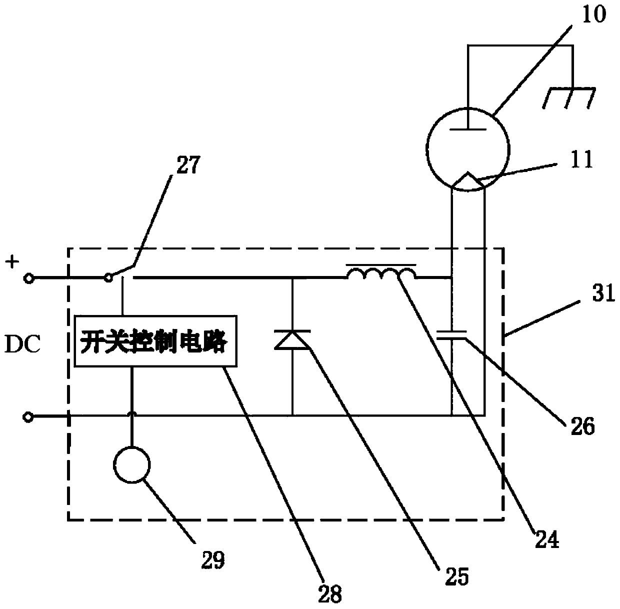
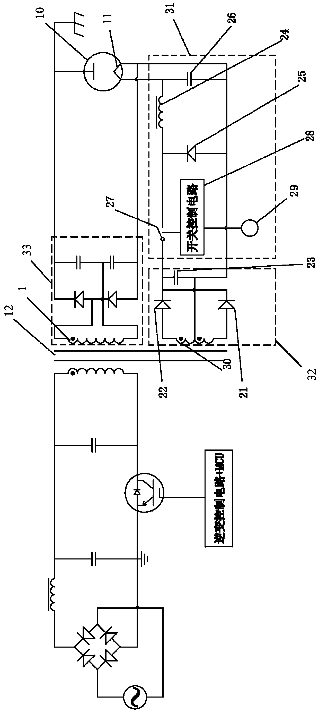
Embodiment Construction

[0047] In describing the present invention, it is to be understood that the terms "upper", "lower", "left", "right", "inner", "outer", "top", "bottom" etc. indicate an orientation or position The relationship is based on the orientation or positional relationship shown in the drawings, and is only for the convenience of describing the present invention and simplifying the description, rather than indicating or implying that the referred device or element must have a specific orientation, be constructed and operated in a specific orientation, therefore It should not be construed as a limitation of the present invention.

[0048] Those skilled in the art can understand that the word "comprising" used in the description of the present invention refers to the existence of the above-mentioned features, integers, steps, operations, elements and / or components, but does not exclude the existence or addition of one or more other features , integers, steps, operations, elements, compone...


PUM


Abstract

Provided are a magnetron filament control circuit and a magnetron power supply circuit, belonging to the field of household electrical appliances. A magnetron (10) filament control circuit (31) comprises: a switch tube (27), connected in series between a flyback diode (25) and a direct-current input terminal; an inductor (24), connected in series to a filament (11) of the magnetron (10) between the two ends of the flyback diode (25); the flyback diode (25) cuts off when the switch tube (27) closes; a temperature sensor (29), configured to detect the temperature of the magnetron (10); a switch control circuit (28), configured to control, according to the temperature of the magnetron (10), the switch tube (27) to close or disconnect, such that if the temperature of the magnetron (10) is within a predetermined threshold range, then the direct current alternating in magnitude and height flows through the filament (11) of the magnetron (10). The temperature sensor (29) and switch control circuit (28) work together so that the current entering the magnetron filament (11) is controlled according to the temperature of the magnetron (10), ensuring that the filament (11) stabilizes transition of electrons.

Description

technical field [0001] The invention relates to the design field of household appliances, in particular to a magnetron filament control circuit, a magnetron power supply circuit and a microwave heating device. Background technique [0002] A magnetron is an electric vacuum device used to generate microwave energy. Essentially a diode placed in a constant magnetic field. Under the control of the perpendicular constant magnetic field and constant electric field, the electrons in the tube interact with the high-frequency electromagnetic field to convert the energy obtained from the constant electric field into microwave energy. [0003] The electrons in the magnetron are generated by the filament (or cathode). There are two main power supply methods for the magnetron filament of the existing frequency conversion microwave oven: one method is to provide a basically stable AC voltage, and the continuous maximum power supply during the whole working process , so as to maintain t...

Claims


Application Information

Patent Timeline
Patent Type & Authority Patents(China)
IPC IPC(8): H05B6/66H02M3/156
CPCH02M3/156H05B6/662H05B2206/043
Inventor 覃承勇黎青海郑年重艾军亮
Owner GUANGDONG MIDEA KITCHEN APPLIANCES MFG CO LTD
Features
  • Generate Ideas
  • Intellectual Property
  • Life Sciences
  • Materials
  • Tech Scout
  • Unparalleled Data Quality
  • Higher Quality Content
  • 60% Fewer Hallucinations
Learn More