
Six-Hall three-output motor rotor position sensor and installation method

A technology of motor rotor and installation method, which is applied in the direction of electromechanical devices, electrical components, electric components, etc., can solve the problems of error, error increase, and the inability of Hall devices to function, and achieve the effect of meeting performance requirements and reducing errors

Pending Publication Date: 2020-12-01
SHANDONG JIAOTONG UNIV
View PDF6 Cites 5 Cited by
  • Summary
  • Abstract
  • Description
  • Claims
  • Application Information

AI Technical Summary

Problems solved by technology

[0006] The inventors found that when the magnetic field changes from negative to positive and gradually increases, the device can output high level only when the magnetic field is greater than the set value, and when the magnetic field changes from positive to negative, the device can Output low level; when the magnetic field changes, there is a hysteresis interval in the change of the output level, resulting in an error in the output of the Hall position sensor, which is caused by the Schmitt trigger inside the Hall sensor; this hysteresis The return interval will cause the level change of the output of the Hall device to lag behind the position change of the induction magnetic ring, resulting in an error; and the change of the magnetic field direction at the junction of the N and S poles of the magnetic ring will cause a weak magnetic field near the junction. It cannot affect the Hall device; it will cause the level change of the Hall device output to lag behind the position change of the induction magnetic ring, which will further increase the error;
[0007] When using the online adjustment method to install and adjust the sensor, due to the existence of the error of the Hall device and the magnetic ring, the jump of the Hall device from high to low can only occur when the boundary line of N and S of the magnetic ring is offset by S distance; However, when the rotor rotates in the reverse direction, it is necessary to cross the entire signal non-response range to realize the signal jump, resulting in the time when the output level of the Hall device changes in the reverse rotation is not on the center line of the stator and rotor teeth, and a certain error occurs. , so that the performance of the motor is not good when starting and running at low speed

Method used


Image

  • Six-Hall three-output motor rotor position sensor and installation method
  • Six-Hall three-output motor rotor position sensor and installation method
  • Six-Hall three-output motor rotor position sensor and installation method

Examples


Embodiment 1

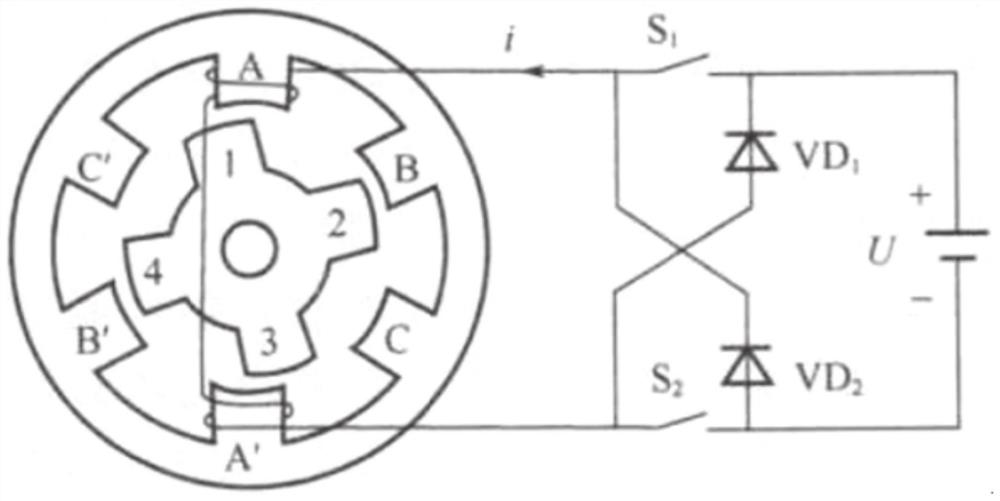
[0082] In a typical implementation of the present disclosure, such as Figure 1-Figure 4 As shown, a six-Hall three-output motor rotor position sensor is proposed.

[0083] There are certain errors in the traditional three-Hall rotor position detection scheme, which brings a lot of inconvenience to the motor control. In order to accurately obtain the position signal of the rotor when the motor rotates in the forward and reverse directions, a position detection scheme of the switched reluctance motor with six Halls and three outputs is proposed.

[0084] Three Hall devices are used to detect the rotor position when the motor is rotating forward, and the other three Hall devices are used to detect the rotor position when the motor is rotating in the reverse direction. In order not to change the number of position detection ports of the motor controller, the six Hall devices The input signal is converted into three output signals by a logic circuit, such as Figure 11 As shown,...

Embodiment 2

[0094] In another typical implementation of the present disclosure, such as Figure 19-Figure 23 As shown, a working method of the six-Hall three-output motor rotor position sensor as described in Embodiment 1 is given.

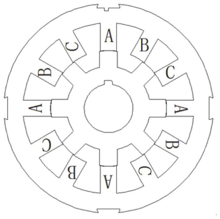
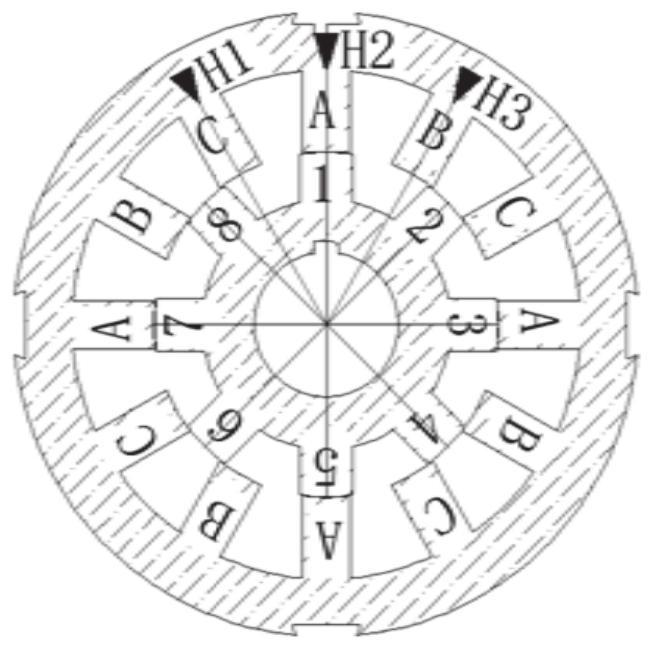
[0095] In order to clearly illustrate the problem, the motor is expanded along the circumference, as shown in Figure 19 shown. In practical application, the magnetic ring is fixed at the proper position of the rotor, and the ideal output signal is obtained by adjusting the positions of the two Hall detection circuit boards. In essence, as long as the position where the centerline of the stator teeth of one phase of the motor is aligned with the centerline of a certain rotor tooth can coincide with the moment when the level of the Hall sensor of this phase jumps, the rotor position of the motor can be accurately positioned. The motor and Hall sensors are deployed along the circumferential direction, and the six Hall devices are installed near the centerline...

Embodiment 3

[0106] In yet another exemplary embodiment of the present disclosure, such as Figure 24-1-Figure 24-6 As shown, a method for installing the rotor position sensor of a six-Hall three-output motor as described in Embodiment 1 is given.

[0107] Include the following steps:

[0108] Arrange the induction magnetic ring on the rotor, and fix the Hall assembly on the motor end cover;

[0109] Energize one phase winding of the motor to drive the rotor to move to align the rotor teeth of one phase with the center line of the stator teeth of one phase;

[0110] Adjust a group of Hall components to rotate in the first direction until the corresponding Hall components jump, fix the group of Hall components, connect and lock with the motor end cover;

[0111] Energize one phase winding of the motor to maintain the alignment of the rotor teeth of one phase with the center line of the stator teeth of one phase;

[0112] Adjust another group of Hall components to rotate in the second dir...


PUM


Abstract

The invention provides a six-Hall three-output motor rotor position sensor and an installation method and belongs to the field of switched reluctance motors. The sensor comprises induction magnetic rings and two groups of Hall assemblies; each group of Hall assemblies comprises three Hall elements; the three Hall elements in the first group are arranged in a manner of respectively and correspondingly facing three continuous stator teeth; the three Hall elements in the second group are arranged in a manner of respectively and correspondingly facing three continuous stator teeth different from the three continuous stator teeth facing the first group; the Hall elements corresponding to the same phase in the two groups of Hall assemblies are connected into the same logic conversion module; a plurality of induction magnetic rings are annularly and uniformly arranged along a rotating shaft and are corresponding to rotor teeth; the butt joint parts of the adjacent induction magnetic rings coincide with the center lines of the corresponding rotor teeth. The two groups of Hall assemblies are arranged to respectively monitor rotor position conditions during forward rotation and reverse rotation; and a logic conversion circuit is adopted to process potential changes during the forward rotation and reverse rotation, so that the accurate monitoring of rotor positions during forward rotationand reverse rotation is realized under the condition of not increasing the number of leads led out of a motor.

Description

technical field [0001] The disclosure relates to the field of switched reluctance motors, in particular to a six-Hall three-output motor rotor position sensor and an installation method. Background technique [0002] The statements in this section merely provide background information related to the present disclosure and may not necessarily constitute prior art. [0003] Switched reluctance motor is a new type of speed control motor, which is the latest generation of speed control system following frequency conversion speed control system and brushless DC motor speed control system. It has simple and firm structure, wide speed range and high system reliability. The complete system mainly consists of motor entity, power converter, controller and position detector. The controller contains the power converter and control circuit, while the rotor position detector is installed at one end of the motor. [0004] The key to the control of the switched reluctance motor is to obt...

Claims


Application Information

Patent Timeline
Patent Type & Authority Applications(China)
IPC IPC(8): H02K11/215
CPCH02K11/215
Inventor 张云王知学谢君王雪娟李小伟侯恩广刘广敏乔昕解兆延王晓红
Owner SHANDONG JIAOTONG UNIV
Features
  • Generate Ideas
  • Intellectual Property
  • Life Sciences
  • Materials
  • Tech Scout
  • Unparalleled Data Quality
  • Higher Quality Content
  • 60% Fewer Hallucinations
Learn More