Pin shearing and bending structure

A pin and bending table technology, applied in the field of bending structure, can solve the problems of wasting manpower and time, and the cutting size and bending angle cannot be guaranteed, so as to achieve the guarantee of cutting size and bending angle, reduce manpower and the effect of time

Inactive Publication Date: 2018-03-09
SHENXUN COMP KUNSHAN
View PDF4 Cites 12 Cited by
  • Summary
  • Abstract
  • Description
  • Claims
  • Application Information

AI Technical Summary

Problems solved by technology

[0006] Therefore, the purpose of the present invention is to provide a pin shearing and bending structure, which solves the problem that the existing process wastes manpower and time, and the shearing size and bending angle cannot be guaranteed.

Method used


Image

  • Pin shearing and bending structure
  • Pin shearing and bending structure
  • Pin shearing and bending structure

Examples


Embodiment Construction

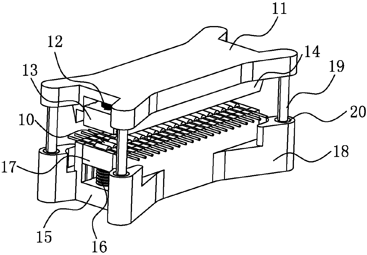
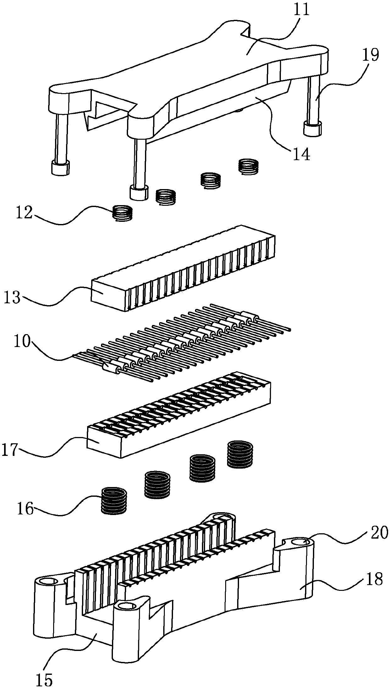
[0021] Please refer to figure 2 , image 3 , figure 2 Illustrated as a schematic diagram of the pin shearing and bending structure of the present invention, image 3 shown as figure 2 Schematic diagram of the breakdown structure.

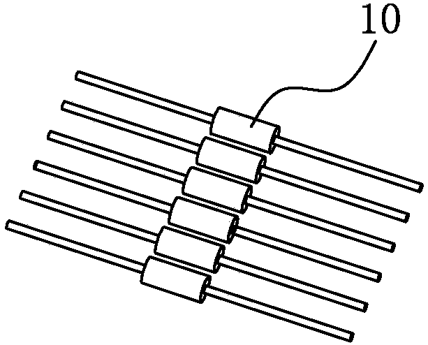
[0022] In order to achieve the above object, the pin shear bending structure of the present invention (for figure 1 Incoming pin 10 for processing), including:

[0023] Upper seat 11, the bottom surface of which is fixedly provided with a first spring 12 (the cushioning of the first spring 12 can better clamp and fix the pair of pins 10), and the lower end of the first spring 12 is fixedly provided with an upper Slider 13, the bottom surface of the upper slider 13 has a first positioning surface, the bottom surface of the upper seat 11 is also extended with a cutter 14, and the cutter 14 extends close to the side of the upper slider 13;

[0024] The lower seat 15 is fixedly provided with a second spring 16 on its top surface, and the upper ...


PUM


Abstract

The invention discloses a pin shearing and bending structure, comprising: an upper seat, the bottom surface of which is fixedly provided with a first spring; Positioning surface, the bottom surface of the upper seat is also extended with a cutter, and the cutter extends close to the side of the upper slider; the lower seat is fixed with a second spring on its top surface, and the upper end of the second spring is held against A lower slider is fixed, the top surface of the lower slider has a second positioning surface, and the top surface of the lower seat is also extended with a bending platform, and the bending platform is set at the side of the lower slider, And the cutting knife reaches the outer position of the bending table after cutting down, and the first positioning surface, the second positioning surface, and the bending table are jointly positioned to place the pin. By adopting the structure, manpower and time can be reduced, and the cutting size and bending angle can be guaranteed.

Description

【Technical field】 [0001] The invention relates to a bending structure, in particular to a pin shearing and bending structure. 【Background technique】 [0002] see figure 1 , figure 1 It is a schematic diagram of a pin incoming material structure. As shown in the figure, the two ends of the pin 10 (pin) of the incoming material are longer, and are usually protected by a protective cover when the incoming material is supplied. According to the needs of use, the two ends of the pin 10 will be cut and bent by 90 degrees. [0003] In the prior art, the two ends of the pin 10 are manually cut to reach the required length, and then the two ends of the cut pin 10 are bent. [0004] However, with the above method, the size and angle cannot be guaranteed due to manual cutting and bending, which is time-consuming and labor-intensive. [0005] In view of this, it is necessary to develop a pin shearing and bending structure to solve the above problems. 【Content of invention】 [00...

Claims


Application Information

Patent Timeline
Patent Type & Authority Applications(China)
IPC IPC(8): B21F1/00B21F11/00
CPCB21F1/004B21F11/00
Inventor 赵瑞国
Owner SHENXUN COMP KUNSHAN
Why Eureka
Try Eureka