Tensile-shear test loading device with flight structure

A technology for loading devices and aeronautical structures, applied to measuring devices, using stable tension/pressure to test the strength of materials, instruments, etc., can solve the problems of not having a large-tonnage tensile testing machine

Inactive Publication Date: 2012-07-25
NANJING UNIV OF AERONAUTICS & ASTRONAUTICS
View PDF6 Cites 30 Cited by
  • Summary
  • Abstract
  • Description
  • Claims
  • Application Information

AI Technical Summary

Problems solved by technology

At present, due to differences in manufacturing and implementation methods, most strength laboratories do not have large-tonnage tensile testing machines, only large-tonnage compression testing machines

Method used


Image

  • Tensile-shear test loading device with flight structure
  • Tensile-shear test loading device with flight structure
  • Tensile-shear test loading device with flight structure

Examples


Embodiment Construction

[0016] Below in conjunction with accompanying drawing, the present invention is described in further detail:

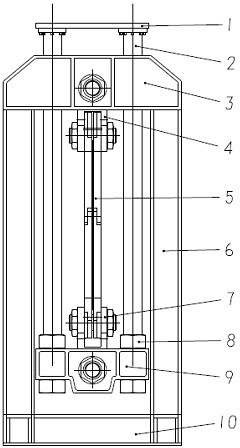
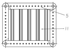
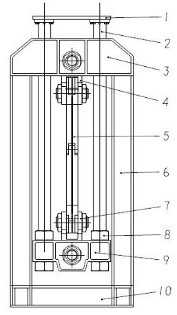
[0017] As shown in the figure: a tensile-shear test loading device for aeronautical structures, including a pressing plate 1, a pressing rod 2, an upper beam 3, an upper cross joint 4, a fixture 5, a column 6, a lower cross joint 7, and a force transmission nut 8 , lower beam 9, base 10.

[0018] The upper end of the base 10 is arranged with a column 6, and the upper beam 3 is arranged at the top of the column 6; The upper cross joint 4 is arranged between the bottom end of the pressure bar 2, the lower cross joint 7 is arranged at the upper end of the lower beam 9 between the pressure bars 2, and the clamp 5 is arranged between the upper cross joint 4 and the lower cross joint 7 . Fixture 5 is composed of four splints, and the four splints are hinged to each other to form a movable quadrilateral structure, in which the two opposite hinged ends are respectively hing...


PUM


Abstract

The invention relates to a test loading device, in particular to a tensile-shear test loading device with a flight structure. Compression bars are arranged between stand columns, the upper ends of the compression bars are extended to form an upper beam, a compression plate is arranged on the top ends of the stand columns, a lower beam is arranged on the bottom ends of the stand columns, an upper cross type joint is arranged between the compression bars on the bottom end of the upper beam, a lower cross type joint is arranged on the upper end of the lower beam between the compression bars; and a fixture is arranged between the upper cross type joint and the lower cross type joint. The test loading device provided by the invention can be used for converting pressure of a compression tester into tensile of a test piece or realizing shear force of the test piece through the action of the fixture, and can be used for a tensile or shear test of stiffened wall plates and similar structures without being provided with a special large loading tensile testing machine independently.

Description

technical field [0001] The invention relates to a test loading device, in particular to a tensile-shear test loading device of an aeronautical structure. Background technique [0002] Parts such as the fuselage, wings and empennage of the aircraft bear most of the load during flight. It can be seen from their structural characteristics that these parts are all thin-walled and reinforced structures. The main failure mode of this structure is buckling, which is manifested as deformation of the surface of the structure. For the wing structure, the deformation of the surface will affect the flow field, thereby affecting the force on the wing, and then affecting the flight safety of the aircraft. Therefore, in the aircraft airworthiness specification, the wing skin is generally not allowed Buckling occurs. [0003] Existing tests are mainly aimed at the reinforced panel structure of the wing or fuselage, and the buckling load and failure load are measured through the buckling a...

Claims


Application Information

Patent Timeline
Patent Type & Authority Applications(China)
IPC IPC(8): G01N3/02G01N3/04G01N3/08
Inventor 朱书华陈智徐建童明波王跃全邹建胜
Owner NANJING UNIV OF AERONAUTICS & ASTRONAUTICS
Why Eureka
Try Eureka