Pressure reducing device for lowering tail pipe

A decompression device and practical technology, which is applied in wellbore/well components, earthwork drilling, flushing wellbore, etc. It can solve the problems affecting the construction progress, the depth of the tailpipe running into the ground, and the leakage of the formation, so as to improve the construction Progress, faster drilling speed, reasonable structure effect

Pending Publication Date: 2018-03-09
BC P INC CHINA NAT PETROLEUM CORP +1
View PDF15 Cites 0 Cited by
  • Summary
  • Abstract
  • Description
  • Claims
  • Application Information

AI Technical Summary

Problems solved by technology

[0002] In the liner cementing operation in oil and gas fields, the normal running speed of the liner will affect the construction progress due to the large liner running depth. When the running speed is accelerated, it is easy to leak the formation, damage the liner and the drilling tool and the oil well The bottom layer will generate exciting pressure; when the lowering speed is reduced, it will cause the sticking of the tail pipe, which will lead to serious engineering accidents

Method used


Image

  • Pressure reducing device for lowering tail pipe
  • Pressure reducing device for lowering tail pipe
  • Pressure reducing device for lowering tail pipe

Examples


Embodiment Construction

[0019] The present invention is not limited by the following examples, and specific implementation methods can be determined according to the technical solutions of the present invention and actual conditions.

[0020] In the present invention, for the convenience of description, the description of the relative positional relationship of each component is based on the description attached to the description. figure 1 For example, the positional relationship of front, rear, top, bottom, left, right, etc. is determined according to the layout direction of the drawings in the description.

[0021] Below in conjunction with embodiment and accompanying drawing, the present invention will be further described:

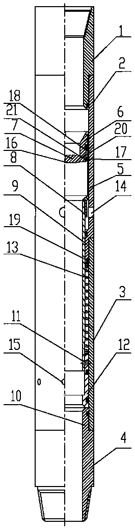
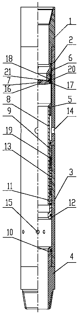
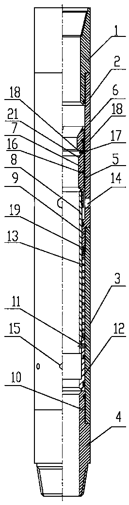
[0022] as attached figure 1 , 2 , 3, 4, 5, and 6, the decompression device for the lower tail pipe includes an upper joint 1, an upper casing 2, a lower casing 3, a lower joint 4, a valve cavity cover 5, a valve seat 6, a leaf valve 7 and The center pipe 8, the outer side...


PUM


Abstract

The invention relates to the technical field of downhole tools and discloses a pressure reducing device for lowering a tail pipe. The pressure reducing device comprises an upper joint, an upper sleeve, a lower sleeve, a lower joint, a valve cavity hood, a valve seat, a blade valve and a center pipe. The outer side of the lower portion of the upper joint and the inner side of the upper portion of the upper sleeve are fixedly mounted together; a sleeve annular table is arranged on the inner side of the lower end of the upper sleeve; and the outer side of the sleeve annular table and the inner side of the upper portion of the lower sleeve are fixedly mounted together. The pressure reducing device provided by the invention is reasonable in structure and convenient to use, and automatic grouting is formed by means of a valve clack through hole in the blade valve; the center pipe moves upward to open a lower circulating hole to communicate the inner side and the outer side; the blade valve is opened by injecting a drilling fluid, so that the center pipe moves downward to cut off a shear pin and the lower circulating hole is closed for follow-up construction, thereby playing a role of a float collar. Surge pressures generated by a leaker stratum and a ground floor of an oil well are prevented as a result of too quick lowering while the drilling speed is accelerated to promote the construction progress, the damage on the tail pipe and the fed drilling tool is reduced, and the pressure reducing device has the characteristics of being reliable, safe and simple and convenient.

Description

technical field [0001] The invention relates to the technical field of downhole tools, and relates to a decompression device for a lower liner. Background technique [0002] In the liner cementing operation in oil and gas fields, the normal running speed of the liner will affect the construction progress due to the large liner running depth. When the running speed is accelerated, it is easy to leak the formation, damage the liner and the drilling tool and the oil well The bottom layer will generate exciting pressure; when the lowering speed is reduced, it will cause the sticking of the tail pipe, which will lead to serious engineering accidents. Contents of the invention [0003] The invention provides a decompression device for the lower liner, which overcomes the above-mentioned deficiencies in the prior art, and can effectively avoid the pressure leakage formation and the bottom layer of the oil well caused by the excessively fast lowering speed while accelerating the d...

Claims


Application Information

Patent Timeline
Patent Type & Authority Applications(China)
IPC IPC(8): E21B33/13E21B21/10
CPCE21B21/10E21B33/13
Inventor 李勇龙高飞张新文郭新超杨光翟亚锋张志君范庆郭建军帕尔哈提·拜克辛勇丁兆奇郭瑞祥
Owner BC P INC CHINA NAT PETROLEUM CORP
Why Eureka
Try Eureka