Improved environmentally-friendly dedusting device

A dust removal device and an improved technology, applied in the installation of vacuum cleaners, cables, and electrical equipment, etc., can solve the problems of waste of power resources, reduced service life, deterioration of the environment and air, etc., to save electricity and reduce the impact , the effect of reducing waste

Inactive Publication Date: 2018-03-13
广州元凛建筑工程技术开发有限公司
View PDF8 Cites 0 Cited by
  • Summary
  • Abstract
  • Description
  • Claims
  • Application Information

AI Technical Summary

Problems solved by technology

[0002] With the development of the industrial age, people's awareness of environmental protection is increasing. In the production of industrial products, a large amount of dust is generated. Without proper dust removal measures, the environment and air in the workshop will be polluted and deteriorated, which will be harmful to the human body. The health of the dust removal equipment is generally used for industrial dust removal. However, due to the strong mobility of the dust removal equipment during the dust removal operation, the power supply line of the existing dust removal equipment is relatively short, and it is difficult to meet the power supply when moving. Needed, when encountering similar phenomena, one or more terminal boards are generally used to extend the connection to achieve the purpose of plugging in and supplying power to the dust removal equipment. However, after multiple terminal boards are connected, the power supply line has a certain length, which is extremely inconvenient when retracting. In addition, if the power supply line is exposed to the outside world for a long time when it is not in use, it will easily cause damage and reduce the service life; there are also many dust removal power supply equipment that can automatically retract and release the line, but it needs to be additionally powered by the mains to control the operation. cause waste of power resources

Method used


Image

  • Improved environmentally-friendly dedusting device
  • Improved environmentally-friendly dedusting device
  • Improved environmentally-friendly dedusting device

Examples


Embodiment Construction

[0023] All features disclosed in this specification, or steps in all methods or processes disclosed, may be combined in any manner, except for mutually exclusive features and / or steps.

[0024] Any feature disclosed in this specification (including any appended claims, abstract and drawings), unless expressly stated otherwise, may be replaced by alternative features which are equivalent or serve a similar purpose. That is, unless expressly stated otherwise, each feature is one example only of a series of equivalent or similar features.

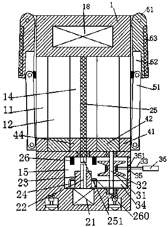
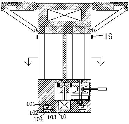
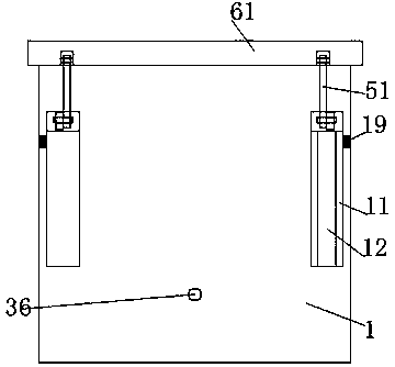
[0025] Such as Figure 1-5 As shown, an improved environmental protection dust removal device of the present invention includes a box shell 1 and a photoelectric conversion part. A control chamber 15 is arranged in the bottom of the box shell 1, and a driving chamber 15 is fixedly installed in the bottom wall of the control chamber 15. machine 21, the top of the driving machine 21 is fixedly provided with a revolving pin shaft 22, and an enga...


PUM


Abstract

Provided is an improved environmentally-friendly dedusting device, including a case housing and a photoelectric conversion portion. The bottom of the case housing is internally provided with an operation cavity. The bottom wall of the operation cavity is internally fixedly provided with a driving machine. The top of the driving machine is fixedly provided with a rotating pin shaft. The rotating pin shaft is slidably provided with a joining pipe sleeve. The joining pipe sleeve is fixedly provided with a dentate wheel. The operation cavity is provided with a dentate plate which is meshed with the dentate wheel through a shaft rod. The shaft rod is also fixedly provided with a reel. A cable is arranged on the reel. The cable is arranged in a hole in a side wall of the operation cavity in a through manner, and extends outward. An anti-wearing ring is arranged in the hole. The anti-wearing ring is abutted against the inner wall of the hole. The tail of the cable is fixedly provided with a power strip. The photoelectric conversion portion comprises placing plates which are corresponding in left and right manner and are rotatably arranged on the upper ends of two side walls of the case housing, and a photoelectric plate fixedly arranged in the placing plate. The case housing is also internally provided with an accumulator connected with the photoelectric plate and the driving machineby circuits. The case housing is also internally provided with a pushing portion.

Description

technical field [0001] The invention relates to the technical field of environmental protection dust removal, in particular to an improved environmental protection dust removal device. Background technique [0002] With the development of the industrial age, people's awareness of environmental protection is increasing. In the production of industrial products, a large amount of dust is generated. Without proper dust removal measures, the environment and air in the workshop will be polluted and deteriorated, which will be harmful to the human body. The health of the dust removal equipment is generally used for industrial dust removal. However, due to the strong mobility of the dust removal equipment during the dust removal operation, the power supply line of the existing dust removal equipment is relatively short, and it is difficult to meet the power supply when moving. Needed, when encountering similar phenomena, one or more terminal boards are generally used to extend the ...

Claims


Application Information

Patent Timeline
IPC IPC(8): A47L9/28A47L9/26
CPCA47L9/2878A47L9/26
Inventor 欧阳翎
Owner 广州元凛建筑工程技术开发有限公司
Why Eureka
Try Eureka