
Novel medical cold closet device

A refrigerated box, a new type of technology, applied in the direction of unloading device, transportation and packaging, packaging of fragile items, etc., can solve the problems of high price, difficult to meet the needs of quick access and storage of blood, intensified shaking of test tubes, etc. safety effect

Inactive Publication Date: 2018-03-13
南宁市泽镁智能科技有限公司
View PDF4 Cites 2 Cited by
  • Summary
  • Abstract
  • Description
  • Claims
  • Application Information

AI Technical Summary

Problems solved by technology

[0002] With the continuous maturity of modern medical technology, the use of medical refrigerators is becoming more and more widely. It is mainly used for cold storage after blood collection. The test tubes are placed in the test tube rack, and the test tube rack is put into the refrigerator for refrigerated storage. However, the test tube is a fragile container, and the traditional medical refrigerator has a single setting mode, which often does not have a locking function. It is difficult to ensure that the blood is not contaminated and the stability is poor. When an accidental collision with the refrigerator occurs, the test tube rack inside will slide relative to the box body. As a result, the shaking of the test tube intensifies, and there is a risk of breaking it. There are many medical refrigerators that can be automatically locked, but they are expensive and the setting mode is too complicated. It is cumbersome and complicated, and it is difficult to meet the needs of quick access or quick storage of blood in medical refrigerators

Method used


Image

  • Novel medical cold closet device
  • Novel medical cold closet device
  • Novel medical cold closet device

Examples


Embodiment Construction

[0024] All features disclosed in this specification, or steps in all methods or processes disclosed, may be combined in any manner, except for mutually exclusive features and / or steps.

[0025] Any feature disclosed in this specification (including any appended claims, abstract and drawings), unless expressly stated otherwise, may be replaced by alternative features which are equivalent or serve a similar purpose. That is, unless expressly stated otherwise, each feature is one example only of a series of equivalent or similar features.

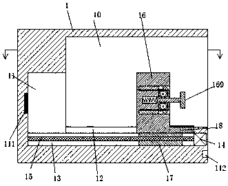
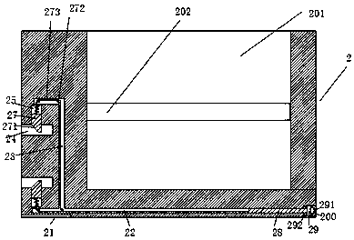
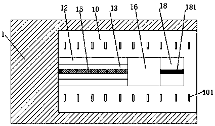
[0026] Such as Figure 1-7 As shown, a new type of medical refrigerator device of the present invention includes a box body 1 and a test tube rack 2. The box body 1 is provided with a cavity 10, and the bottom wall of the cavity 10 is provided with a left-right extension A sliding groove 12, the bottom wall of the first sliding groove 12 is provided with a second sliding groove 13 extending left and right, and a sliding block 17 is installed ...


PUM


Abstract

A new type of medical refrigerator device, including a box body and a test tube rack. A cavity is arranged in the box body, a first sliding groove extending left and right is arranged in the bottom wall of the cavity, and a left and right extending groove is arranged in the bottom wall of the first sliding groove. The second sliding groove, the sliding block is installed in the second sliding groove to slide left and right, the screw thread in the sliding block is equipped with a screw rod, and the left end of the screw rod is rotatably installed on the second In the left end wall of the sliding groove, the right end is connected to the motor fixedly installed in the right end wall of the second sliding groove, and a sliding piece is installed in the first sliding groove so as to slide left and right, and the sliding piece is fixedly connected with the sliding block , the right end of the sliding part is fixedly installed with a bearing plate, and the supporting plate is provided with a card strip extending left and right. The second shifting groove with the mouth facing right is mutually called, and a communicating groove is arranged between the first shifting groove and the second shifting groove, and a toothed wheel is rotatably installed in the communicating groove.

Description

technical field [0001] The invention relates to the technical field of medical equipment, in particular to a novel medical refrigerator device. Background technique [0002] With the continuous maturity of modern medical technology, the use of medical refrigerators is becoming more and more widely. It is mainly used for cold storage after blood collection. The test tubes are placed in the test tube rack, and the test tube rack is put into the refrigerator for refrigerated storage. However, the test tube is a fragile container, and the traditional medical refrigerator has a single setting mode, which often does not have a locking function. It is difficult to ensure that the blood is not contaminated and the stability is poor. When an accidental collision with the refrigerator occurs, the test tube rack inside will slide relative to the box body. As a result, the shaking of the test tube intensifies, and there is a risk of breaking it. There are many medical refrigerators tha...

Claims


Application Information

Patent Timeline
Patent Type & Authority Applications(China)
IPC IPC(8): B65D25/10B65D25/52B65D81/18B65D85/30
CPCB65D25/10B65D25/52B65D81/18B65D85/30
Inventor 裴欢
Owner 南宁市泽镁智能科技有限公司
Learn More