Mechanism and method for locking and unlocking urban rail transit semi-high shielding door

A technology of urban rail transit and unlocking mechanism, applied in the field of rail transit screen door/safety door locking equipment, can solve the problems of large space occupation, high manufacturing cost, inconvenient maintenance, etc., and achieve the effect of ensuring normal operation

Inactive Publication Date: 2018-03-13
XIAN RAILWAY SIGNAL
11 Cites 1 Cited by

AI-Extracted Technical Summary

Problems solved by technology

The existing structure takes up a lot of space, is inc...

Abstract

The invention belongs to rail transit shielding door/safety door locking equipment, and relates to an electronic locking device applicable for rail transit semi-high shielding door locking equipment,in particular to a mechanism and method for locking and unlocking an urban rail transit semi-high shielding door. The mechanism is characterized by at least comprising a swing handle (1), a guide wheel component (2), connecting steel wires (3), an unlocking component (4), a lock (5), an electromagnetic locking component (6), a travel switch (7), a locking component (8) and an electromagnet (9); the handle (1) is connected to the unlocking component (4) through the guide wheel component (2) by virtue of the connecting steel wires (3); and the unlocking component (4) is connected to the lock through a lever; the unlocking component (4) is connected to the lock which is provided with the electromagnetic locking component (6). The mechanism and method for locking and unlocking the urban rail transit semi-high shielding door have the advantages of a simple structure, easy maintenance, installation space saving and low manufacturing and maintenance cost.

Application Domain

Non-mechanical controls

Technology Topic

EngineeringMechanical engineering +3

Image

  • Mechanism and method for locking and unlocking urban rail transit semi-high shielding door
  • Mechanism and method for locking and unlocking urban rail transit semi-high shielding door
  • Mechanism and method for locking and unlocking urban rail transit semi-high shielding door

Examples

  • Experimental program(1)

Example Embodiment

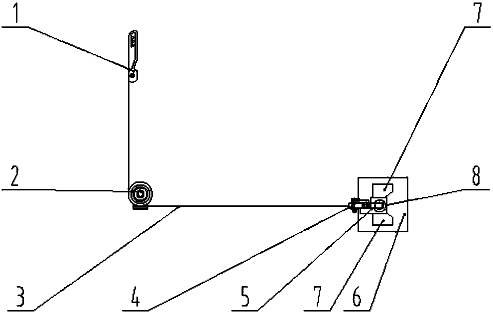
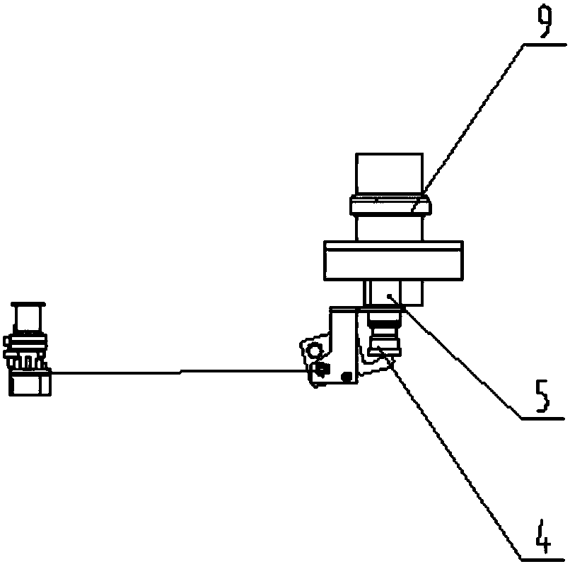
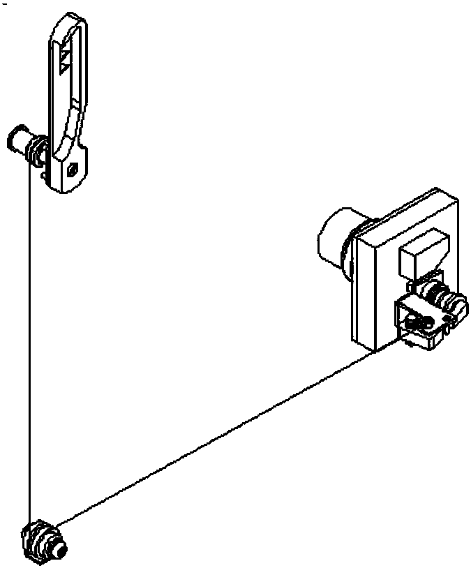
[0021] Such as figure 1 , figure 2 , image 3 As shown, an urban rail transit half-height shielded door locking and unlocking mechanism is provided, which is characterized in that it at least includes: a rotating handle 1, a guide wheel assembly 2, a connecting wire 3, an unlocking assembly 4, a lock 5, and an electromagnetic locking assembly 6. , Stroke switch 7, locking assembly 8, electromagnet 9, device fasteners. The fasteners are mainly used to connect the entire device to the door. The handle 1 is connected to the unlocking assembly 4 through the connecting wire 3 through the guide wheel assembly 2; The assembly 4 is connected with the lock head 5 through a lever; the unlocking assembly 4 is connected with the lock head 5, and the lock head 5 has an electromagnetic locking assembly 6 on it.
[0022] As shown in FIG. 7, the electromagnetic lock assembly 6 includes a travel switch 7, a lock assembly 8, and an electromagnet 9. The travel switch 7 and the electromagnet 9 are connected to the lock assembly 8 respectively. The electromagnetic locking assembly 6 is mainly used for locking the lock. Normally, the electromagnetic locking assembly 6 is installed inside the door side box through the mounting seat. During the unlocking process, the electromagnet 9 is energized, and the locking assembly 8 is attracted by the electromagnet. Under the action of, it can move in the axial direction, that is, the direction C as shown in Figure 7. The unlocking component 4 (area 2) is composed of the unlocking component 4, the lock head 5 and the device fasteners. Normally, the component will be fixed in the mounting bracket On the door guide rail, during the door opening/closing movement, the door moves linearly along the A direction shown in Figure 7. When the door is closed, the lock head 5 moves along the A direction and is about to reach the locking position. When the closing component 8 collides, the locking component 8 will be affected by the lift force under the action of the collision force to realize the locking function. When the door needs to be manually unlocked, under the action of the unlocking force, the unlocking assembly 4 rotates along the axis of rotation shown in FIG. 7 so that the unlocking assembly 4 and the locking assembly 8 are displaced in the B direction to realize the unlocking function and ensure the door The body opens normally.
[0023] Locking process: such as Figure 4 , The door body and the lock head 5 move from the initial position (the door is in the normal open state) to the locked position. During this process, the door body drives the lock head 5 to move linearly along the A direction. After the lock head 5 collides with the electromagnetic locking assembly 6 , Under the action of lift, the electromagnetic locking assembly 6 moves linearly along the B direction, and at the same time the stroke switch 7 detects the locking signal, after the lock head 5 moves to the locking position, the entire mechanism completes the automatic locking and detection process;
[0024] Automatic unlocking process: such as Figure 5 , The electromagnetic locking component 6 is energized, the electromagnet is magnetic, the attracting and locking component 8 moves linearly along the C direction, and the lock head 5 and the locking component 8 are displaced along the C direction to achieve separation, and the entire mechanism completes the automatic unlocking function
[0025] Manual unlocking process: such as Image 6 , Rotate the handle or turn the key, and drive the connecting wire to move linearly along the D direction through the guide assembly, thereby driving the lock head 5 to move linearly along the E direction. The lock head 5 and the locking assembly 6 are displaced along the E direction to achieve separation. The entire mechanism is manually completed Unlock function.

PUM

no PUM

Description & Claims & Application Information

We can also present the details of the Description, Claims and Application information to help users get a comprehensive understanding of the technical details of the patent, such as background art, summary of invention, brief description of drawings, description of embodiments, and other original content. On the other hand, users can also determine the specific scope of protection of the technology through the list of claims; as well as understand the changes in the life cycle of the technology with the presentation of the patent timeline. Login to view more.

Similar technology patents

Straw pellet boiler

InactiveCN102287920AGuaranteed uptimeReduce the degree of generation
Owner:SHANDONG DUOLE HEATING EQUIP

Cluster fault analysis method based on event-driven analysis

InactiveCN104657622AImprove analysis and resolution efficiencyGuaranteed uptime
Owner:INSPUR GROUP CO LTD

Limit load identification method for wind power generator unit

ActiveCN105422391AGuaranteed uptimeReduce ultimate load
Owner:CSR ZHUZHOU ELECTRIC LOCOMOTIVE RES INST

Absorption roller and machining device of sheet product

PendingCN110467036AGuaranteed uptimehigh traffic
Owner:FOSHAN BAOSUO PAPER MASCH MFG CO LTD

Classification and recommendation of technical efficacy words

  • Guaranteed uptime

Air conditioner defrosting control method

InactiveCN107702293AGuaranteed heating effectGuaranteed uptime
Owner:QINGDAO HAIER AIR CONDITIONING ELECTRONICS CO LTD

Method and device for detecting discs

ActiveCN102147708AGuaranteed uptime
Owner:CHENGDU HUAWEI TECH

Switching-over method

Owner:HUAWEI TECH CO LTD

Resintered fused silica brick and method of producing the same

InactiveCN101172872AGood thermal stability and thermal shock resistanceGuaranteed uptime
Owner:孙邢哲
Why Eureka
Try Eureka