A diaphragm spring compensation type mechanical seal device

A mechanical seal device, diaphragm spring technology, applied in the direction of engine seal, mechanical equipment, engine components, etc., can solve the problem of unsatisfactory follow-up between the dynamic ring and the static ring, inconvenient installation, maintenance, disassembly, and reduced mechanical seal performance, etc. problem, to achieve the effect of compact structure, simple structure and improved sealing performance

Active Publication Date: 2019-08-23
JINCHENG NANJING ELECTROMECHANICAL HYDRAULIC PRESSURE ENG RES CENT AVIATION IND OF CHINA
View PDF7 Cites 0 Cited by
  • Summary
  • Abstract
  • Description
  • Claims
  • Application Information

AI Technical Summary

Problems solved by technology

But there are some problems as follows: the structure is too complicated and there are too many assembly parts, which brings great inconvenience to the installation, maintenance and disassembly of the product
Most of the existing mechanical seal compensation systems use multiple coil springs so that the tracking performance of the moving ring and the static ring is not ideal
The frictional heat generated between the moving ring and the static ring of the traditional mechanical seal cannot be well dissipated, causing the end face to deform due to uneven heating. In severe cases, the seal end face will crack, which greatly reduces the performance of the mechanical seal.
Even cause the mechanical seal to fail

Method used


Image

  • A diaphragm spring compensation type mechanical seal device
  • A diaphragm spring compensation type mechanical seal device
  • A diaphragm spring compensation type mechanical seal device

Examples


Embodiment Construction

[0053] The present invention will be described in detail below with reference to the drawings and specific embodiments.

[0054] The structure of the embodiment of the present invention is as Figure 1 to Figure 9 Shown.

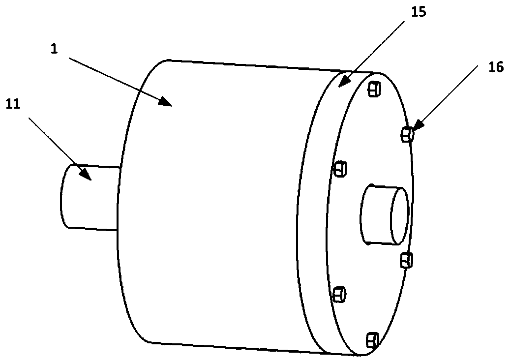
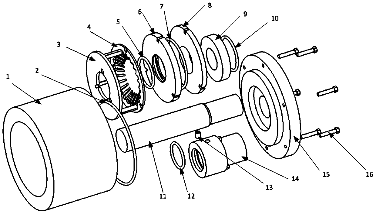
[0055] The invention provides a diaphragm spring compensation type mechanical seal device, which comprises a moving ring component, a static ring component, a rotating shaft component, a shell component and a gland component. The relationship between them is that the moving ring assembly is sleeved on the rotating shaft assembly, the static ring assembly is sleeved on the rotating shaft empty, and the moving ring assembly and the static ring assembly form a sealing surface through surface contact. The shell assembly and the gland assembly are fastened by bolts, and the entire moving ring assembly, the static ring assembly and the rotating shaft assembly are contained in the cavity of the shell to form a rotating shaft end sealing device.

[0056] The moving ring ...


PUM


Abstract

The invention provides a diaphragm spring compensation type mechanical sealing device which comprises a movable ring assembly, a stationary ring assembly, a rotating shaft assembly, a housing assemblyand a gland assembly, wherein the movable ring assembly sleeves the rotating shaft assembly with a space; the stationary ring assembly sleeves the rotating shaft with a space; the movable ring assembly and the stationary ring assembly form a sealing surface through surface contact; and the housing assembly and the gland assembly are fastened and connected through bolts, and the entire movable ring assembly, the stationary ring assembly and the rotating shaft assembly are contained in a cavity of a housing so that a shaft end sealing device is formed. The diaphragm spring compensation type mechanical sealing device is simple in mechanical sealing structure and compact in structure, production, machining and later transportation, mounting and maintenance are facilitated, the use cost is reduced substantially, and pre-tightening force borne by a movable ring is uniform. The movable ring is designed to be in a cylindrical step structure, the integral heat dissipation of the movable ring is facilitated, and the sealing property can be improved more.

Description

Technical field [0001] The invention provides a diaphragm spring compensation type mechanical seal device, in particular to a rotating shaft sealing technology in a fluid seal, and belongs to the technical field of mechanical seals. Background technique [0002] The mechanical seal is an axial end face sealing device that relies on the pre-tensioning of the dynamic and static ring end face seal pairs by the elastic element and the compression of the medium pressure and the pressure of the elastic element to achieve the seal, so it is also called the end face seal. Mechanical seals are widely used in equipment such as centrifugal pumps, centrifuges, reactors and compressors. With the rapid development of the industrial field, practical applications require mechanical seals to adapt to frequent extreme working conditions such as high pressure, high speed, or starting and stopping, and variable working conditions. This puts higher requirements on the performance of mechanical seals....

Claims


Application Information

Patent Timeline
Patent Type & Authority Patents(China)
IPC IPC(8): F16J15/34F16J15/32
Inventor 郭生荣卢岳良刘胜任春宇
Owner JINCHENG NANJING ELECTROMECHANICAL HYDRAULIC PRESSURE ENG RES CENT AVIATION IND OF CHINA
Why Eureka
Try Eureka