Virtual signal injection-based maximum torque current ratio control method of synchronous motor
A technology of maximum torque current and virtual signal, which is applied in the field of maximum torque current ratio control based on virtual signal injection, can solve problems such as motor efficiency reduction, stator current increase, d-axis current reference value deviation, etc., to ensure stable State accuracy, improve the effect of response
Active Publication Date: 2018-03-13
ZHEJIANG UNIV
View PDF5 Cites 17 Cited by
- Summary
- Abstract
- Description
- Claims
- Application Information
AI Technical Summary
Problems solved by technology
[0004] However, during the operation of the motor, due to the influence of iron core saturation and temperature rise, L d , L q and ψ f will change, so the d-axis current refere
Method used
View moreImage
Smart ImageViewing Examples
Examples
 PUM
 Abstract
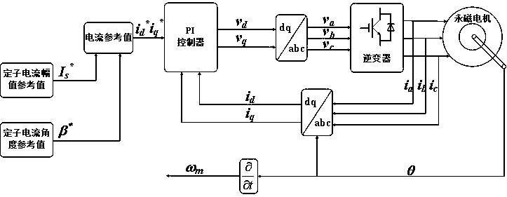
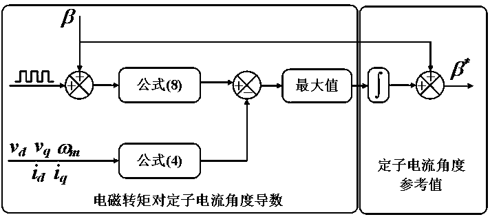
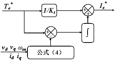
The invention discloses a virtual signal injection-based maximum torque current ratio control method of a synchronous motor. A tidy signal is injected to a stator current angle to obtain a derivativeof an electromagnetic torque on the stator current angle, and then a stator current angle reference value is obtained; and next, a stator current amplitude reference value is obtained by a fixed torque constant and an open loop compensation integrator, and then a d-q-axis current reference value is obtained. By virtue of the more accurate formula disclosed in the invention, the steady state precision is ensured; and by virtue of square wave injection and processing method, dynamic response is improved.
Description
technical field [0001] The invention relates to a maximum torque current ratio control of a permanent magnet synchronous motor, in particular to a maximum torque current ratio control based on virtual signal injection. Background technique [0002] Due to the anisotropy of the magnetic circuit, the d-axis and q-axis inductance of the interior permanent magnet synchronous motor are not equal, so the torque of the interior permanent magnet synchronous motor includes two parts: permanent magnet torque and reluctance torque. There is an optimal combination between these two parts, so that the stator current is the smallest under the same torque. This operating state is called the maximum torque current ratio control. [0003] In order to obtain the d-q-axis current reference value at the maximum torque-current ratio, the common method is to first obtain the q-axis current reference value through the speed loop, and then pass a d-axis inductance L d , q-axis inductance L q and ...
Claims
Login to View More Application Information
Patent Timeline
 IPC IPC(8): H02P21/22H02P21/20
Inventor 黄晓艳王俊方攸同
Owner ZHEJIANG UNIV
Features
- R&D
- Intellectual Property
- Life Sciences
- Materials
- Tech Scout
- Unparalleled Data Quality
- Higher Quality Content
- 60% Fewer Hallucinations
Learn More Browse by: Latest US Patents, China's latest patents, Technical Efficacy Thesaurus, Application Domain, Technology Topic, Popular Technical Reports.
© 2025 PatSnap. All rights reserved.Legal|Privacy policy|Modern Slavery Act Transparency Statement|Sitemap|About US| Contact US: help@patsnap.com


