
A minimum loss control method for surface-mounted permanent magnet synchronous motors

A permanent magnet synchronous motor, loss control technology, applied in motor generator control, electronic commutation motor control, control system and other directions, can solve problems such as insufficient motor efficiency, difficult adjustment of regulator parameters, and insufficient system response speed. , to ensure fast dynamic response, small steady-state loss, and steady-state accuracy

Inactive Publication Date: 2019-04-23
XI AN JIAOTONG UNIV
View PDF3 Cites 0 Cited by
  • Summary
  • Abstract
  • Description
  • Claims
  • Application Information

AI Technical Summary

Problems solved by technology

However, the classic vector control system does not consider the influence of motor iron loss and other factors, and uses a PID regulator, which has problems such as insufficient system response speed, insufficient motor efficiency, and difficult adjustment of regulator parameters, making it difficult to meet increasingly stringent application requirements.

Method used


Image

  • A minimum loss control method for surface-mounted permanent magnet synchronous motors
  • A minimum loss control method for surface-mounted permanent magnet synchronous motors
  • A minimum loss control method for surface-mounted permanent magnet synchronous motors

Examples


Embodiment Construction

[0040] The present invention will be described in further detail below in conjunction with the accompanying drawings and specific embodiments.

[0041] According to the above detailed introduction to the minimum loss control method of the surface-mounted permanent magnet synchronous motor, the specific implementation of the present invention will be described below by taking the minimum loss control of a surface-mounted permanent magnet synchronous motor whose parameters are shown in Table 1 as an example. .

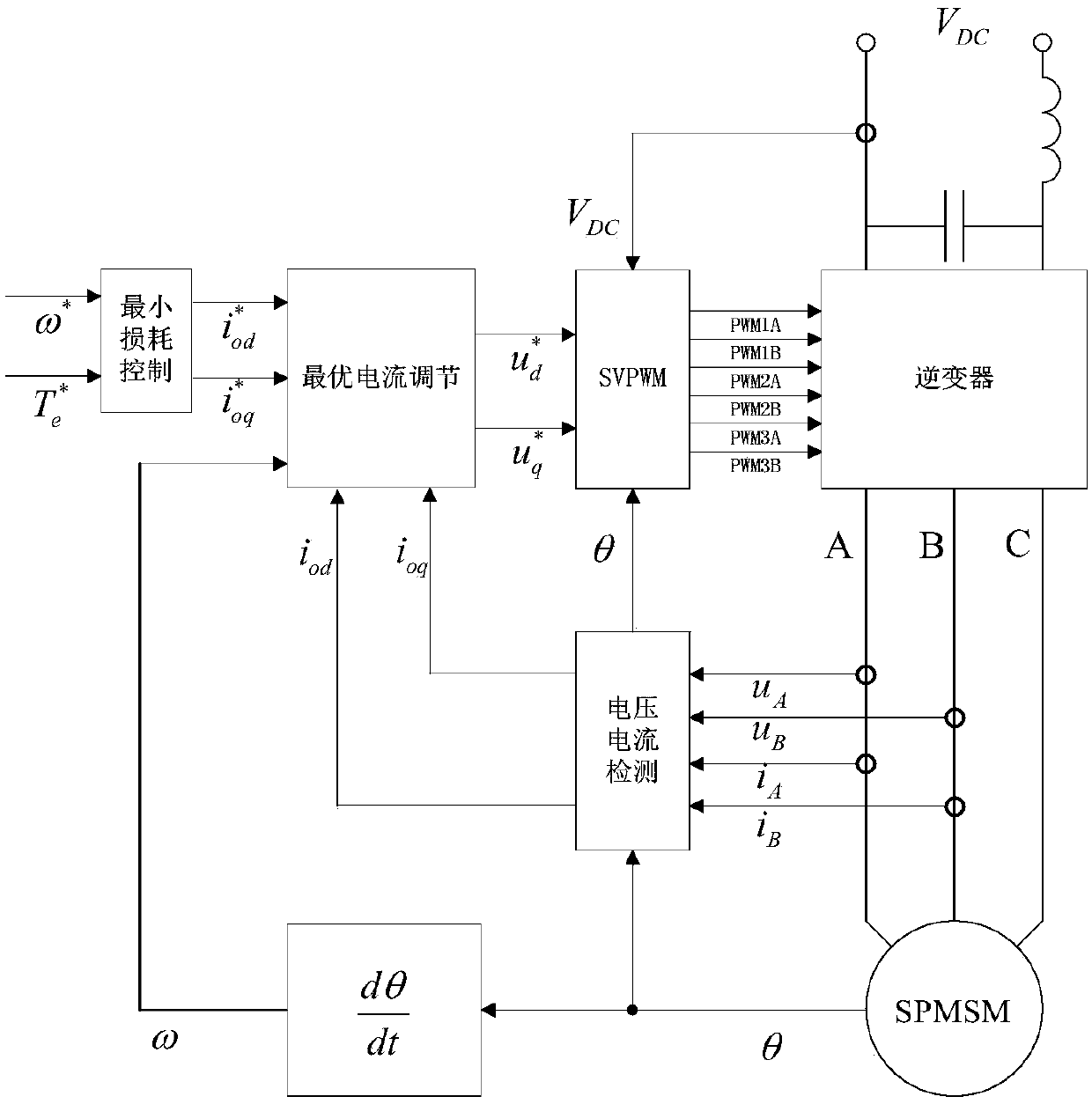
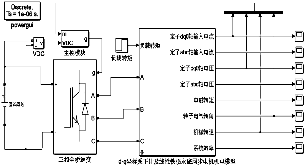
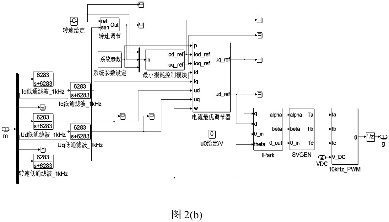
[0042] according to figure 1 The schematic diagram of the minimum loss control of surface-mounted permanent magnet synchronous motor based on the loss model is shown. The simulation model of the minimum loss control system of surface-mounted permanent magnet synchronous motor is built on the MATLAB / SIMULINK simulation software, as shown in figure 2 As shown in (a), the internal structure of the main control module is as follows figure 2 (b) Shown, the inverter switch...


PUM


Abstract

The invention discloses a method for controlling loss minimization of a surface-mounted permanent magnet synchronous motor. The method comprises the following steps: 1, calculating specified exciting currents, leading to loss minimization, of d and q axes of the motor according to a Lagrange multiplier method according to a specified revolving speed and a specified electromagnetic torque; 2, calculating the exciting currents of the d and q axes according to the electric angle of a motor rotor, an A phase voltage, a B phase voltage and the current; 3, calculating specified voltages of the d and q axes according to the electric angular speed of the motor rotor, the exciting currents of the d and q axes, and the specified exciting currents of the d and q axes; 4, converting the specified voltages of the d and q axes into specified voltages in a three-phase static coordinate by using equipower two-phase rotating to three-phase static conversion; 5, producing 6 paths of SVPWM signals according to the specific voltages in the three-phase static coordinate to drive to 6 bridge arms of an inverter used for driving the motor, so as to control the loss minimization of the surface-mounted permanent magnet synchronous motor. The minimization of the steady loss is realized while a vector control system of the surface-mounted permanent magnet synchronous motor guarantees the dynamic response speediness and the steady accuracy.

Description

technical field [0001] The invention belongs to the field of motor control, and in particular relates to a minimum loss control method of a surface-mounted permanent magnet synchronous motor. Background technique [0002] The surface-mounted permanent magnet synchronous motor has the characteristics of small size, low noise, high efficiency, high power density, small moment of inertia, wide speed range, large starting torque, strong overload capacity, and stable output torque. It is widely used in Industrial robots, CNC machine tools, electric vehicles, medical equipment, aircraft and other applications that require high precision, high dynamic performance, and a wide range of position, speed, and torque control. The surface-mounted permanent magnet synchronous motor is a multi-input multi-output, high-order, nonlinear, and strong-coupling system. In order to obtain high dynamic and static performance, it is often controlled by a vector control system. However, the classic ...

Claims


Application Information

Patent Timeline
Patent Type & Authority Patents(China)
IPC IPC(8): H02P21/26H02P21/22
CPCH02P21/22H02P21/26
Inventor 沈传文唐千龙张立宇杨文
Owner XI AN JIAOTONG UNIV
Learn More