Pressing machine for shoe uppers

A technology for pressing machine and shoe upper, which is applied in the direction of shoe-making machinery, shoe uppers, footwear, etc., to achieve the effect of safe operation and avoiding scalding accidents

Inactive Publication Date: 2018-03-16
杜健敏
View PDF6 Cites 1 Cited by
  • Summary
  • Abstract
  • Description
  • Claims
  • Application Information

AI Technical Summary

Problems solved by technology

[0005] In view of the deficiencies in the prior art above, the purpose of the present invention is to provide a vamp pressing machine, which aims to solve the problem that the existing vamp pressing machine needs to directly adjust the contact area between the vamp component and the lower mold by hand.

Method used


Image

  • Pressing machine for shoe uppers

Examples


Embodiment Construction

[0015] The present invention provides a shoe upper pressing machine. In order to make the purpose, technical solution and effect of the present invention clearer and clearer, the present invention will be further described in detail below with reference to the accompanying drawings and examples. It should be understood that the specific embodiments described here are only used to explain the present invention, not to limit the present invention.

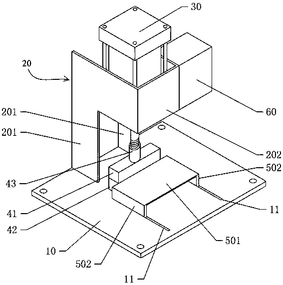
[0016] see figure 1 , The invention provides a vamp pressing machine.

[0017] The shoe upper pressing machine includes a base plate 10, a support frame 20 arranged on the base plate, a cylinder 30 arranged on the support frame, and an upper mold 41 connected to the end of the cylinder piston rod 43, which is arranged on the base plate And be positioned at the lower mold 42 directly below this upper mold, and the workbench that is arranged on the bottom plate; The described upper mold 41 and the lower mold 42 are all rectangular str...


PUM


Abstract

The invention discloses a pressing machine for shoe uppers. The pressing machine comprises a baseplate, a supporting rack, an air cylinder, an upper die, a lower die and a workbench; a first heating tube is arranged in the upper die; two long grooves which are parallel to each other are formed in the baseplate; the workbench comprises a top plate and two vertical plates which are arranged at two ends of the top plate, and the two vertical plates are inserted in the corresponding long grooves and can move along the long grooves linearly; the upper surface of the top plate is parallel to and level with the upper surface of the lower die. According to the pressing machine for shoe uppers, the workbench is moved so that the contact area of a shoe upper component and the lower die can be adjusted, the machine is operated more safely, and scald accidents are avoided.

Description

technical field [0001] The invention relates to the technical field of shoemaking, in particular to a vamp pressing machine. Background technique [0002] When making uppers, it is usually necessary to press and iron the upper parts to make the upper parts more flat; Pressing to flatten and thin the edges and seams of upper components, and ultimately to make the entire upper more aesthetically pleasing. Existing vamp pressing machine [0003] The working tower of the existing shoe upper pressing machine is fixed on the bottom plate, and the contact area between the shoe upper part and the lower mold needs to be directly adjusted by hand, and the upper mold or the lower mold is provided with a heat pipe, which is very easy to cause burn accidents. [0004] It can be seen that the prior art still needs to be improved and enhanced. Contents of the invention [0005] In view of the deficiencies of the prior art above, the object of the present invention is to provide a vamp...

Claims


Application Information

Patent Timeline
Patent Type & Authority Applications(China)
IPC IPC(8): A43D95/02A43D11/04
CPCA43D95/02A43D11/04
Inventor 杜健敏
Owner 杜健敏
Why Eureka
Try Eureka