Control method, device and system of current collector
A control method and technology of current collectors, applied in the direction of current collectors, power collectors, transportation and packaging, etc., can solve the problems of shortened service life and large wear of current collectors, so as to reduce wear, solve large wear and improve use. effect of life
- Summary
- Abstract
- Description
- Claims
- Application Information
AI Technical Summary
Problems solved by technology
Method used
Image

Examples
Example Embodiment
[0028] Example 1
[0029] According to an embodiment of the present invention, an embodiment of a method for controlling a receiver is provided. It should be noted that the steps shown in the flowchart of the accompanying drawings can be executed in a computer system such as a set of computer-executable instructions, and Although the logical sequence is shown in the flowchart, in some cases, the steps shown or described may be performed in a different order than here.
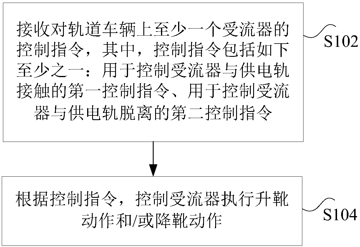
[0030] figure 1 Is a flow chart of a method for controlling a current receiver according to an embodiment of the present invention, such as figure 1 As shown, the method includes the following steps:
[0031] Step S102: Receive a control instruction for at least one current receiver on the rail vehicle, where the control instruction includes at least one of the following: a first control instruction for controlling the current receiver to contact the power rail, and a first control command for controlling the current ...
Example Embodiment
[0066] Example 2
[0067] According to the embodiment of the present invention, there is also provided a system embodiment for implementing the above-mentioned current receiver control method, Figure 7 It is a schematic diagram of a current receiver control system according to an embodiment of the present invention, such as Figure 7 As shown, the system includes: at least one current receiver 701, an input device 703 and a control device 705.
[0068] Among them, at least one current collector 701 is deployed on at least one carriage of the rail vehicle;
[0069] The input device 703 is used to receive a control instruction for at least one receiver on the rail vehicle, where the control instruction includes at least one of the following: a first control instruction for controlling the receiver to contact the power rail, and a first control instruction for controlling the receiver The second control command that the inverter is separated from the power supply rail;
[0070] The cont...
Example Embodiment
[0087] Example 3
[0088] According to the embodiment of the present invention, there is also provided an embodiment of an apparatus for implementing the control method of the above-mentioned current receiver, Figure 13 It is a schematic diagram of a control device of a current receiver according to an embodiment of the present invention, such as Figure 13 As shown, the device includes: a receiving unit 131 and a control unit 133.
[0089] Wherein, the receiving unit 131 is configured to receive a control instruction for at least one current receiver on the rail vehicle, where the control instruction includes at least one of the following: a first control instruction for controlling the current receiver to contact the power supply rail; The second control command to control the separation of the current receiver from the power supply rail;
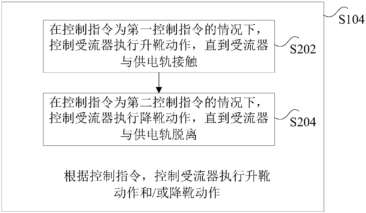
[0090] The control unit 133 is configured to control the current receiver to perform a boot-up action and / or a boot-down action according to...
PUM
 Abstract
Description
Claims
Application Information
 - R&D Engineer
- R&D Manager
- IP Professional
- Industry Leading Data Capabilities
- Powerful AI technology
- Patent DNA Extraction
Browse by: Latest US Patents, China's latest patents, Technical Efficacy Thesaurus, Application Domain, Technology Topic.
© 2024 PatSnap. All rights reserved.Legal|Privacy policy|Modern Slavery Act Transparency Statement|Sitemap