Wire take-up device for electric power

A wire take-up device and electric power technology, which is applied in the directions of transportation and packaging, transportation of filamentous materials, and thin material handling, etc., can solve the problems of disordered winding order, high cost, and low winding efficiency of optical fiber ribbons, and reduce labor force. , Improve work efficiency and facilitate loading and unloading

Inactive Publication Date: 2018-03-16
李笑美
View PDF0 Cites 6 Cited by
  • Summary
  • Abstract
  • Description
  • Claims
  • Application Information

AI Technical Summary

Problems solved by technology

[0002] With the development of communication technology, a large number of FTTX networks are laid, so the demand for cables is increasing day by day. At present, the winding efficiency of optical fiber ribbons is low and the cost is high. Therefore, the efficiency of optical fiber ribbon winding needs to be improved. The take-up reel is a cable storage tool. , the cable wraps around it for easy access
[0003] The take-up reel in the current technology usually includes a spool for the cable to be wound and baffles arranged at both ends of the spool to prevent the wound cable from falling off from the two ends of the spool. When the cable is taken up, the cable is wound on the spool , although the take-up reel with this structure can achieve the purpose of taking up the cable, but the cable is freely wound on the bobbin, which easily leads to disordered order of winding

Method used


Image

  • Wire take-up device for electric power
  • Wire take-up device for electric power
  • Wire take-up device for electric power

Examples


Embodiment Construction

[0018] The following will clearly and completely describe the technical solutions in the embodiments of the present invention with reference to the accompanying drawings in the embodiments of the present invention. Obviously, the described embodiments are only some, not all, embodiments of the present invention. Based on the embodiments of the present invention, all other embodiments obtained by persons of ordinary skill in the art without making creative efforts belong to the protection scope of the present invention.

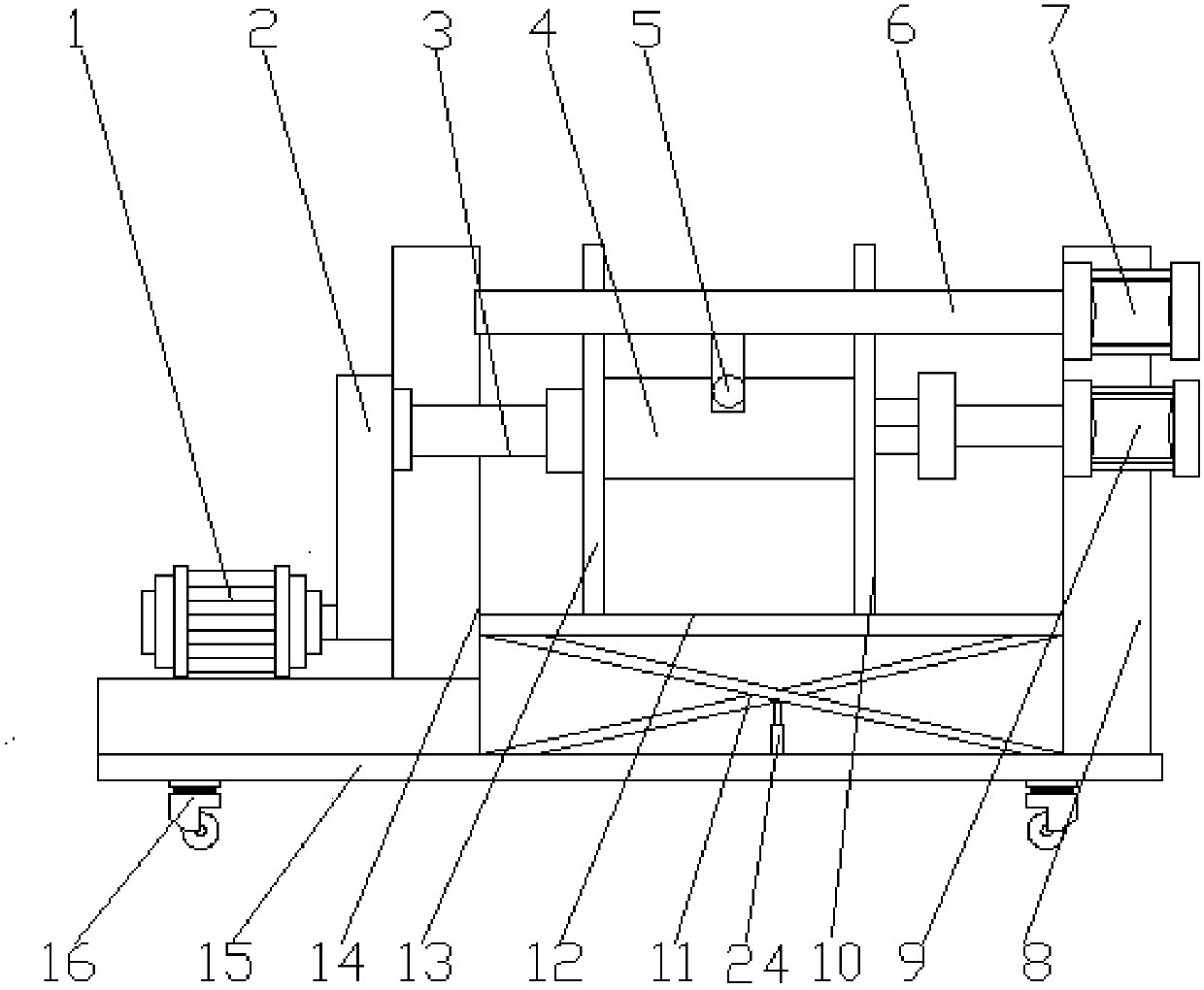
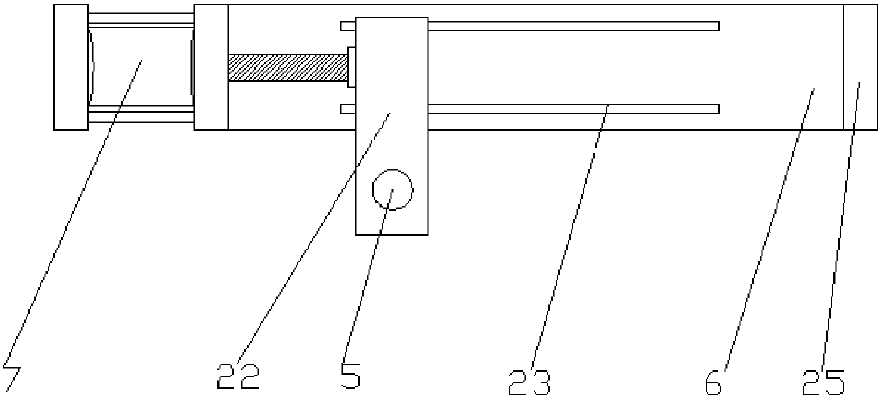
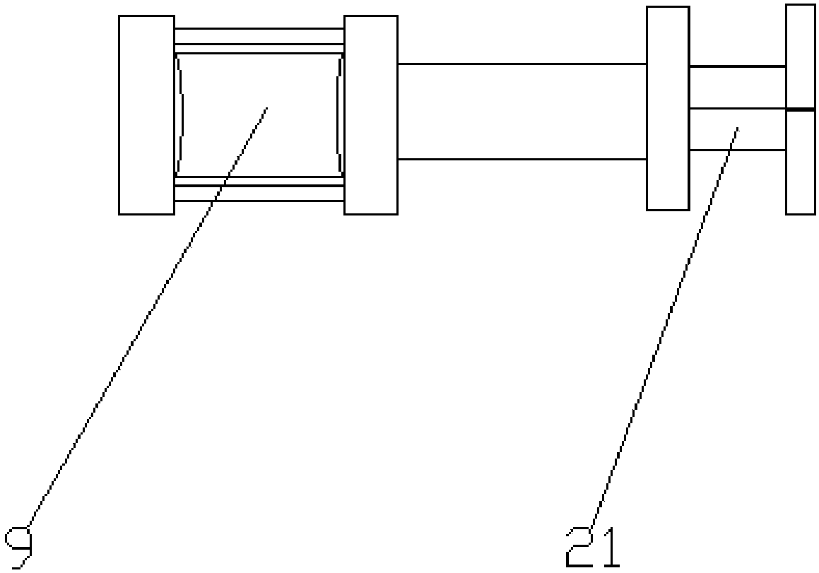
[0019] see Figure 1-6 , an embodiment provided by the present invention: a wire take-up device for electric power, including a motor 1, a wire take-up turntable 4, a first support column 8, a second support column 14 and a base 15, characterized in that: the base 15 The top of the first support column 8 and the second support column 14 are fixed, the upper end of the second support column 14 is equipped with a rotating shaft 3 through a bearing, and the rotat...


PUM


Abstract

The invention discloses a wire take-up device for electric power, comprising a motor, a wire take-up turntable, a first support column, a second support column and a base, the first support column and the second support column are fixed above the base, the The upper end of the second supporting column is equipped with a rotating shaft through a bearing, and the rotating shaft runs through the second supporting column. One end of the rotating shaft is equipped with a take-up turntable, and the two ends of the take-up turntable are respectively fixed with a first limiting plate and a second The limit plate, the upper end of the first support column is respectively equipped with a first cylinder and a second cylinder, the output end of the second cylinder is equipped with a jaw, and the gap between the first support column and the second support column A fixed rod is fixed on the upper end, and a chute is provided on the side of the fixed rod, and a motor is fixed on the base on one side of the second support column. The wire take-up device for electric power of the present invention can keep winding orderly, is convenient for loading and unloading, reduces labor intensity, improves work efficiency, and is convenient to use.

Description

technical field [0001] The invention relates to the technical field of electric power equipment, in particular to a wire take-up device for electric power. Background technique [0002] With the development of communication technology, a large number of FTTX networks are laid, so the demand for cables is increasing day by day. At present, the winding efficiency of optical fiber ribbons is low and the cost is high. Therefore, the efficiency of optical fiber ribbon winding needs to be improved. The take-up reel is a cable storage tool. , the cable wraps around it for easy access. [0003] The take-up reel in the current technology usually includes a spool for the cable to be wound and baffles that are arranged at both ends of the spool to prevent the wound cable from falling off from the two ends of the spool. When the cable is taken up, the cable is wound on the spool Although the take-up reel of this structure can achieve the purpose of taking up the cable, the cable is fre...

Claims


Application Information

Patent Timeline
Patent Type & Authority Applications(China)
IPC IPC(8): B65H54/38B65H54/70B65H54/72B65H57/06B65H67/04
CPCB65H54/38B65H54/70B65H54/72B65H57/06B65H67/0411B65H2701/32
Inventor 不公告发明人
Owner 李笑美
Why Eureka
Try Eureka