Slag scraper device with ratchet tooth-ratchet wheel locking and unlocking mechanism

A slag scraping device and ratchet technology, applied in the direction of injection device, can solve the problems of high cost, difficult maintenance and complex structure, and achieve the effect of effectively scraping slag, improving efficiency and ensuring safety.

Pending Publication Date: 2018-03-23
朱殿兴
View PDF7 Cites 0 Cited by
  • Summary
  • Abstract
  • Description
  • Claims
  • Application Information

AI Technical Summary

Problems solved by technology

[0002] Spraying is an important process step in industrial production. It is involved in industries such as automobiles, furniture, and packaging. Spraying is generally carried out in a spray booth. The agent after spraying paint flows into the li

Method used


Image

  • Slag scraper device with ratchet tooth-ratchet wheel locking and unlocking mechanism
  • Slag scraper device with ratchet tooth-ratchet wheel locking and unlocking mechanism
  • Slag scraper device with ratchet tooth-ratchet wheel locking and unlocking mechanism

Examples


Embodiment Construction

[0018] The technical solutions of the present invention will be further described below in conjunction with specific embodiments.

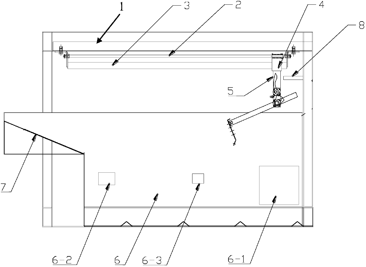
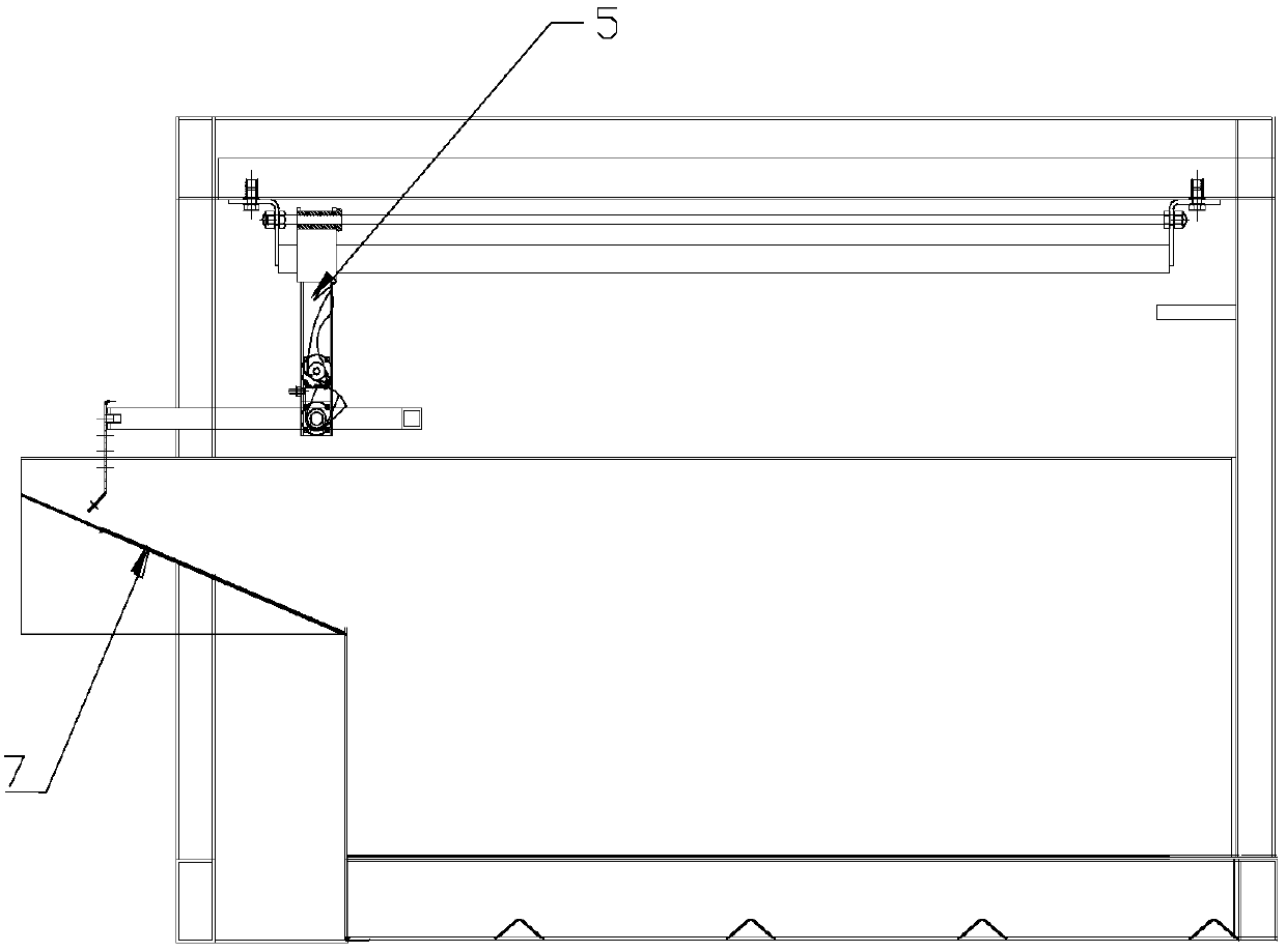
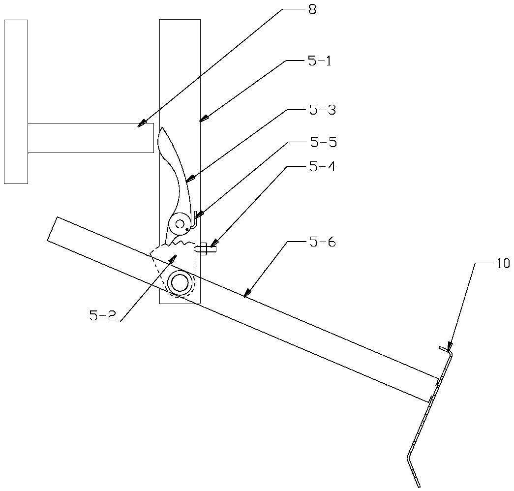
[0019] A kind of slag scraping equipment specially used to clean up paint slag in the spray booth, see the accompanying drawings, the equipment includes frame 1, guide rail 2, cylinder 3, moving trolley 4, ratchet ratchet locking mechanism 5 and liquid storage tank 6. The frame 1 is fixed above the liquid storage tank 6 through a steel structure, the guide rail 2 and the cylinder 3 are horizontally installed on the frame 1, the moving trolley 4 is slidably installed on the guide rail and connected with the action end of the cylinder, and the moving trolley 4 is controlled by the cylinder. Drive, and described ratchet ratchet lock release mechanism 5 is installed on the mobile trolley.

[0020] The cylinder is a stainless steel rod cylinder, and the movement is controlled by compressed air, and the movement speed can be adjusted arbitrarily through...


PUM


Abstract

The invention discloses a slag scraper device with a ratchet tooth-ratchet wheel locking and unlocking mechanism. The slag scraper device comprises the ratchet tooth-ratchet wheel locking and unlocking mechanism and a movable trolley. The ratchet tooth-ratchet wheel locking and unlocking mechanism is mounted on the movable trolley. The movable trolley is slidably mounted on a guide rail and connected with a driving part. The ratchet tooth-ratchet wheel locking and unlocking mechanism comprises a vertical rod, a ratchet wheel, a ratchet tooth, an adjustable limiting screw, a return spring and amovable adjusting rod. A slag scraper is fixedly mounted at the front end of the movable adjusting rod. The movable adjusting rod is hinged to the lower portion of the vertical rod. The ratchet wheelis fixedly mounted at the hinge joint of the movable adjusting rod. The ratchet tooth matched with the ratchet wheel is rotationally mounted on the vertical rod. The adjustable limiting screw is mounted on the part, between the movable adjusting rod and the ratchet tooth, of the vertical rod. The top end of the limiting screw is used for limiting the rotation position of the ratchet wheel so thatthe lowermost position of the movable adjusting rod and the slag scraper can be limited. The return spring is mounted between the ratchet tooth and the vertical rod and provides power for return of the ratchet tooth.

Description

technical field [0001] The invention belongs to the technical field of slag scraping equipment, and in particular relates to a slag scraping device with a ratchet and ratchet locking and releasing mechanism. Background technique [0002] Spraying is an important process step in industrial production. It is involved in industries such as automobiles, furniture, and packaging. Spraying is generally carried out in a spray booth. The agent after painting flows into the liquid storage tank, and paint slag will be formed on the surface of the liquid at this time. The device for collecting paint scum on the liquid surface in the prior art has complex structure, high cost, difficult maintenance and low efficiency. Contents of the invention [0003] The purpose of the present invention is to overcome the deficiencies of the prior art, and provide a slag scraping device with a ratchet and ratchet locking and releasing mechanism. [0004] The present invention is achieved through th...

Claims


Application Information

Patent Timeline
IPC IPC(8): B05B15/00
CPCB05B15/00
Inventor 朱殿兴
Owner 朱殿兴
Why Eureka
Try Eureka