Valve element and valve comprising valve element

A valve core and valve technology, applied in the direction of valve lift, valve details, valve device, etc., can solve the problems of sealing failure, sealing ring easy to come out, etc., and achieve the effect of prolonging service life, enhancing sealing effect, and ingenious design

Pending Publication Date: 2020-01-31
QINGDAO HENGXIN PLASTIC RUBBER CO LTD
View PDF0 Cites 0 Cited by
  • Summary
  • Abstract
  • Description
  • Claims
  • Application Information

AI Technical Summary

Problems solved by technology

[0004] At present, the common valves mainly include ball valves and butterfly valves, which are widely used, but there are many problems. During the rotation of ball valves and butterfly valves, the sealing rings are continuously squeezed. During the rotation, the sealing rings are easily damaged. prolapse, causing seal failure

Method used


Image

  • Valve element and valve comprising valve element
  • Valve element and valve comprising valve element
  • Valve element and valve comprising valve element

Examples


Embodiment 1

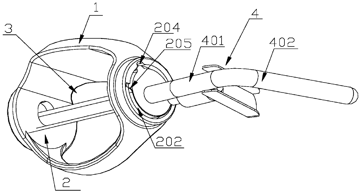
[0048] refer to Figure 1-Figure 7 , the connecting end 2 is oppositely fixed on the same side of the sealing end 1 , the sealing end 1 includes a sealing plate 101 and a sealing ring 102 , and the sealing ring 102 is fixed on the sealing plate 101 . The sealing ring 102 is located on the side away from the connecting end 2, the sealing plate 101 is circular, the diameter of the sealing ring 102 is smaller than the diameter of the sealing plate 101, when the sealing end 1 is in a sealed state , the sealing ring 102 abuts against the liquid outlet 5 . In order to strengthen the sealing effect between the seal ring 102 and the liquid outlet 5, a tapered guide surface 103 is fixedly arranged between the periphery of the seal ring 102 and the edge of the seal plate 101. In this embodiment, the tapered guide surface 103 and the seal The plate 101 and the sealing ring 102 are integrally structured. When the sealing ring 102 is in contact with the liquid outlet 5 and tends to be sea...

Embodiment 2

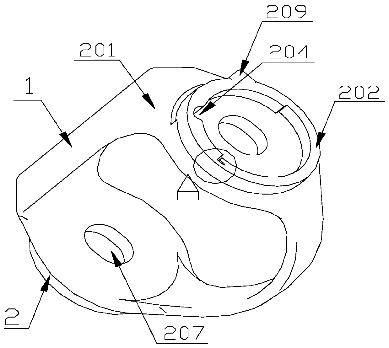
[0053] refer to Figure 1-Figure 4 The rotating shaft 4 includes a rotating shaft body 401 and a handle part 402 in an integrated structure, the rotating shaft body 401 is bent upwards to form a handle part 402, and a limited fixed block is movably connected at the joint between the rotating shaft body 401 and the handle part 402, so A limiting block 403 is fixed on the limiting and fixing block. Specifically, positioning pins are fixed on both sides of the rotating shaft body 401 , and the limiting and fixing block is movably connected with the rotating shaft 4 through the positioning pins. The shaft body 401 extends into the valve body to cooperate with the valve core, and the handle portion 402 is located outside the valve body. Specifically, the shaft body 401 passes through the second through hole 208 and the first through hole in sequence. The hole 207 matches with the connecting end 2 . Meanwhile, the shape of the cross section of the shaft body 401 is the same as tha...

Embodiment 3

[0055] refer to Figure 1-Figure 3 , Figure 8-Figure 10 , on both sides of the inner wall of the valve body, there are two installation grooves 7 for accommodating the connecting end 2, the installation grooves 7 are arranged along the length direction of the valve body, and the two installation grooves 7 are arranged at intervals, and the installation Two limiting grooves 701 are arranged in the groove 7 at intervals, and the limiting grooves 701 are used for accommodating the limiting protrusion 209 . That is to say, when the rotating shaft body 401 rotates, the limiting protrusion 209 moves in the two limiting grooves 701 , and the existence of the limiting protrusion 209 and the limiting groove 701 effectively limits the rotation of the rotating shaft body 401 . While the rotating shaft body 401 is rotating, the switching between the parallel state and the non-parallel state of the plane where the sealing end 1 and the liquid outlet 5 are located is realized.

[0056] I...


PUM


Abstract

The invention relates to a valve element and a valve comprising the valve element, and belongs to the field of valve equipment. The valve comprises a valve body and the valve element; a liquid outletand a liquid inlet are formed in the two ends of the valve body; the valve element is positioned in the valve body, and comprises a sealing end, a connecting end, an opening end and a rotating shaft;the connecting end is relatively fixed on the same side of the sealing end; the opening end is positioned between the connecting end and the sealing end, and is used for enabling fluids to pass through; the rotating shaft penetrates through the connecting end; and the connecting end realizes rotation and linear movement along with rotation of the rotating shaft to realize closing and opening of the valve. A sealing pad cannot be rotated along with the valve element, and is not rubbed with the inner wall of the valve body, so that the service life of the valve is greatly prolonged; and the valve has the characteristics of simple structure and convenient operation, and achieves broad popularization prospect.

Description

technical field [0001] The invention belongs to the technical field of valve equipment, and in particular relates to a valve core and a valve including the valve core. Background technique [0002] The valve is a control component in the fluid delivery system, which has functions such as cut-off, adjustment, flow diversion, reverse flow prevention, pressure stabilization, flow diversion or overflow pressure relief. [0003] Valves used in fluid control systems range from the simplest cut-off valves to various valves used in extremely complex automatic control systems, with a wide variety of varieties and specifications. Valves can be used to control the flow of various types of fluids such as air, water, steam, various corrosive media, mud, oil, liquid metal and radioactive media. [0004] At present, the common valves mainly include ball valves and butterfly valves, which are widely used, but there are many problems. During the rotation of ball valves and butterfly valves,...

Claims


Application Information

Patent Timeline
Patent Type & Authority Applications(China)
IPC IPC(8): F16K1/36F16K1/32F16K1/22F16K1/226F16K27/02
CPCF16K1/2263F16K1/32F16K1/36F16K27/0218
Inventor 姜鹏卞慎坤姜法宏张辉崔建李桂金
Owner QINGDAO HENGXIN PLASTIC RUBBER CO LTD
Why Eureka
Try Eureka