
System and method for machining integral blisks with auxiliary flushing electrolytic milling

An integral blisk and milling technology, which is applied in the field of electrolytic grinding combined processing, can solve the problems of restricting the promotion and industrial application of electrolytic milling and grinding processing technology, poor processing stability, and reduced electrolyte flow rate, etc., to achieve improved processing Stability, promote rapid discharge, reduce loss effect

Active Publication Date: 2019-11-12
NANJING UNIV OF AERONAUTICS & ASTRONAUTICS
View PDF13 Cites 0 Cited by
  • Summary
  • Abstract
  • Description
  • Claims
  • Application Information

AI Technical Summary

Problems solved by technology

However, due to the large flow resistance of the electrolyte in the machining gap and the rotation of the tool cathode during machining, a large amount of electrolyte will be lost rapidly in the processed area, resulting in a decrease in the electrolyte flow rate and uneven flow velocity distribution in the machining gap. It is easy to cause poor processing stability, which is not conducive to improving processing efficiency
This problem seriously restricts the promotion and industrial application of electrolytic milling and grinding technology in the field of rough machining of blisk slots

Method used


Image

  • System and method for machining integral blisks with auxiliary flushing electrolytic milling
  • System and method for machining integral blisks with auxiliary flushing electrolytic milling
  • System and method for machining integral blisks with auxiliary flushing electrolytic milling

Examples


Embodiment Construction

[0028] The present invention will be further described in detail below in conjunction with the drawings.

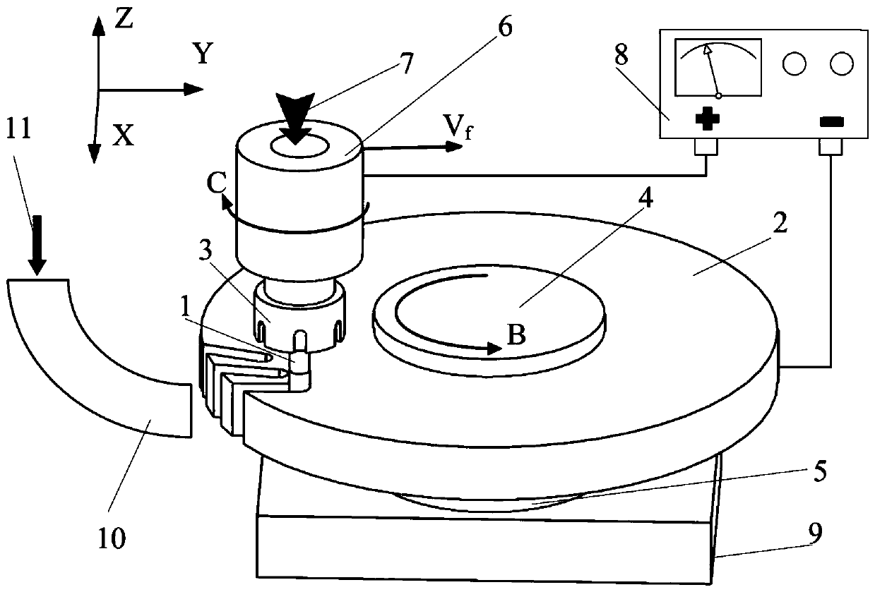
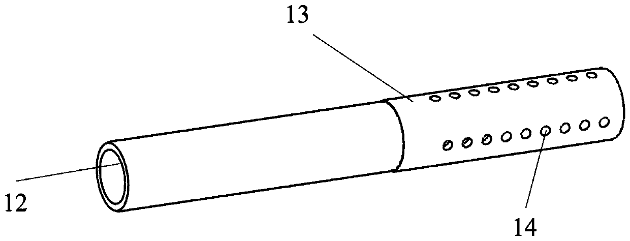
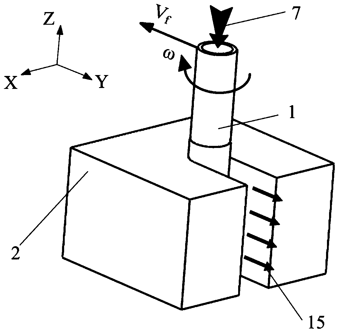
[0029] Such as figure 1 , figure 2 with Figure 4 As shown, the tool cathode 1 is clamped on the end of the main shaft 6 with a through hole through the chuck nut 3, and the blisk blank 2 is clamped on the support shaft 5 of the worktable 9 through the pressing plate 4. The tool cathode 1 is connected to the negative electrode of the power source 8, and the blisk blank 2 is connected to the positive electrode of the power source 8. The tool cathode 1 has blind holes 12 and a number of liquid outlet holes, and is plated with a diamond abrasive grain layer 13. The auxiliary nozzle 10 has the same cross-sectional shape as the groove processed by the blisk blank 2 and faces the surface to be processed of the blisk blank 2. The tool cathode 1 is positioned between the auxiliary nozzle 10 and the surface to be processed of the blisk blank 2 before processing, and maintains a s...


PUM


Abstract

The invention relates to a blisk electrolytic milling machining system and method adopting auxiliary liquid flushing and belongs to the field of electrolytic milling compound machining. The blisk electrolytic milling machining system adopting auxiliary liquid flushing comprises a power source, a tool cathode (1), a main shaft (6), a blisk blank (2), a supporting shaft (5) and an auxiliary spray nozzle (10). The auxiliary spray nozzle (10) is provided with a section identical with a groove to be machined in shape and is right opposite to a to-be-machined face of the blisk blank (2). The tool cathode (1) is located between the auxiliary spray nozzle (1) and the to-be-machined face of the blisk blank (2), and initial intervals are kept between the tool cathode (1) and the auxiliary spray nozzle (1) and the to-be-machined face of the blisk blank (2). During machining, the tool cathode (1) and the auxiliary spray nozzle (10) supply electrolyte to the machining area of the blisk blank (2) atthe same time, and the pressure of the electrolyte in the auxiliary spray nozzle (10) is larger than that of the electrolyte in the tool cathode (1). By the adoption of the liquid flushing-assisted electrolytic milling machining system and method for the blisk, flow of the electrolyte in a machined area can be effectively restrained, the flow field uniformity in the machining intervals is improved, and the electrolytic milling machining efficiency and stability of the blisk are improved.

Description

Technical field [0001] The invention relates to a system and method for processing an integrated blisk with auxiliary flushing electrolytic milling and grinding, and belongs to the field of electrolytic grinding compound processing. Background technique [0002] The integral blisk is one of the core components of the new aero-engine, and its quality determines the performance and life of the engine. The integral blisk integrates the blade and the wheel disc, eliminating the need for traditional connection of tenon, tongue and groove and locking device, thereby reducing the number of parts and structural weight, avoiding the loss of overflow pressure, and making the aero engine work The efficiency and push-to-weight ratio have been greatly improved. The overall blisk is mostly made of difficult-to-cut materials such as titanium alloy and high-temperature alloy. The forging blank is generally short cylindrical. During the processing from the blank to the finished product, about 90...

Claims


Application Information

Patent Timeline
Patent Type & Authority Patents(China)
IPC IPC(8): B23H5/06
CPCB23H5/06
Inventor 曲宁松牛屾岳小康李寒松
Owner NANJING UNIV OF AERONAUTICS & ASTRONAUTICS
Learn More