Brace-shaped steel wire welding fixture in sextant seat cushion skeleton

A welding jig and steel wire technology, applied in welding equipment, auxiliary welding equipment, welding/cutting auxiliary equipment, etc., can solve the problems of increased welding difficulty, difficult positioning welding, and deformation of steel wire, so as to ensure the balance of force and facilitate the The effect of positioning and ensuring accuracy

Active Publication Date: 2018-03-23
重庆朝旺机械制造有限公司
View PDF6 Cites 5 Cited by
  • Summary
  • Abstract
  • Description
  • Claims
  • Application Information

AI Technical Summary

Problems solved by technology

[0002] There are many kinds of steel wires welded in the frame of the six-point seat cushion, such as figure 2 Shown: It includes the frame tube, the seat front brace steel wire located on the front side of the frame tube, the seat side brace steel wire located on the left side of the frame tube, and the connecting arms located at both ends of the rear side of the frame tube, and various steel wires are prone to deformation , it is not easy to position and weld, and at the same time, it is necessary to ensure that the positioning of the connecting arm and the frame tube is accurate, the positioning of the connecting hole on the connecting arm is accurate, and the quality of later assembly is ensured. Therefore, the difficulty of welding the entire structure is greatly increased. Therefore, in order to solve this problem, it is necessary to A welding fixture that can accurately position the frame tube and various parts to ensure the accuracy of their connection

Method used


Image

  • Brace-shaped steel wire welding fixture in sextant seat cushion skeleton
  • Brace-shaped steel wire welding fixture in sextant seat cushion skeleton
  • Brace-shaped steel wire welding fixture in sextant seat cushion skeleton

Examples


Embodiment

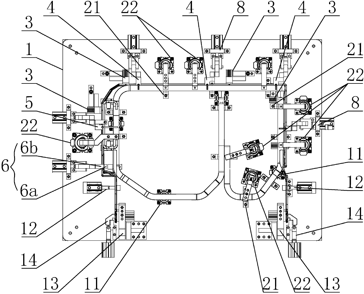
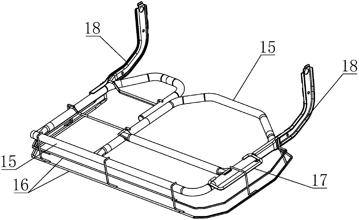
[0032] Such as figure 1 with 2 As shown in and 6: a six-point seat cushion frame middle brace steel wire welding fixture, consisting of a bottom plate 1 used to place the components of the seat cushion frame, a positioning mechanism provided on the bottom plate, a lifting card seat 3, a first The compression block 4, the second compression block 5, the clamping block 6 and the seat side support-shaped steel wire positioning block 7; the positioning mechanism is evenly distributed along the frame tube and supports positioning, such as Picture 9 Shown: the lifting card seat 3 is composed of a slot seat 3a provided with a limiting wire and a pin 3b pushed and clamped by the cylinder, and the lifting card seat 3 is evenly distributed along the lower side of the front support-shaped wire While lifting the limit, the first compression block 4 is located at the front and right side of the seat front brace steel wire and presses the seat front brace steel wire to the frame tube, the s...


PUM


Abstract

The invention discloses a brace-shaped steel wire welding fixture in a sextant seat cushion skeleton. The brace-shaped steel wire welding fixture includes a bottom plate, positioning mechanisms, lifting clamping seats, first pressing blocks, second pressing blocks, a clamping block and a seat side brace-shaped steel wire positioning block, wherein the positioning mechanism, the lifting clamping seat, the first pressing blocks, the second pressing blocks, the clamping block and the seat side brace-shaped steel wire positioning block are arranged on the bottom plate. The positioning mechanisms are distributed evenly along a frame pipe and used for supporting and positioning. The lifting clamping seats are uniformly distributed along the lower side of a seat front brace-shaped steel wire andused for lifting and limiting. The first pressing blocks are located the front side and the right side of the seat front brace-shaped steel wire and presses the seat front brace-shaped steel wire towards the frame pipe. The seat side brace-shaped steel wire positioning block is located at the front end and the back end of a seat side brace-shaped steel wire and used for supporting and limiting. The clamping block corresponds to the seat front brace-shaped steel wire at the left side and the seat side brace-shaped steel wire, and the seat front brace-shaped steel wire and the seat side brace-shaped steel wire are pressed synchronously. By means of the brace-shaped steel wire welding fixture, each part is independently positioned and clamped, positions are reasonably distributed, stress balance is ensured, positioning of the steel wires is facilitated, the bracing effect after welding of the steel wires is ensured, meanwhile, the accuracy of the hole positioning is ensured through a holepositioning connecting arm and a connecting bracket.

Description

Technical field [0001] The invention belongs to the technical field of seat frame welding, and specifically relates to a brace steel wire welding fixture in a six-point seat cushion frame. Background technique [0002] The six-point seat cushion frame is welded by a variety of steel wires, such as figure 2 Shown: it includes the frame tube, the seat front brace steel wire on the front side of the frame tube, the seat side brace wire on the left side of the frame tube, and the connecting arms on the rear ends of the frame tube. Various types of steel wires are prone to deformation. , It is not easy to position and weld. At the same time, it is necessary to ensure the accurate positioning of the connecting arm and the frame tube, ensure the accurate positioning of the connecting hole on the connecting arm, and ensure the quality of later assembly. Therefore, the welding difficulty of the entire structure is greatly increased. Therefore, in order to solve this problem, it is necessar...

Claims


Application Information

Patent Timeline
Patent Type & Authority Applications(China)
IPC IPC(8): B23K37/04
CPCB23K37/0435
Inventor 杨松林何雪冰廖腾军
Owner 重庆朝旺机械制造有限公司
Why Eureka
Try Eureka