Loading and swing conveying device for automobile seat shaft clamping bolts

A technology of clamping and installing the seat shaft, which is applied in the direction of positioning device, clamping, support, etc., and can solve the problem of inconvenient and fast installation or disassembly of the mounting seat, inclination angle of non-adjustable device placement, and inaccurate flipping and clamping bolts, etc. problems, to achieve good social and economic benefits, easy and quick installation or disassembly, compact and reliable installation

Active Publication Date: 2018-03-23
抚州中垣实业有限公司
View PDF7 Cites 0 Cited by
  • Summary
  • Abstract
  • Description
  • Claims
  • Application Information

AI Technical Summary

Problems solved by technology

[0002] The existing installation and swinging device for the car seat shaft clamping bolt has a fixed device position and cannot adjust the inclination angle of the device. Low working efficiency, poor quality, large floor area of ​​the device, most of the parts of the mounting base are welded, the installation or disassembly of the mounting base is not convenient and fast enough, the clamping pin is easy to fall off when installing and placing it, and the mounting is not firm enough Shortcomings

Method used


Image

  • Loading and swing conveying device for automobile seat shaft clamping bolts
  • Loading and swing conveying device for automobile seat shaft clamping bolts
  • Loading and swing conveying device for automobile seat shaft clamping bolts

Examples


Embodiment Construction

[0020] The preferred embodiments of the present invention will be described in detail below in conjunction with the accompanying drawings, so that the advantages and features of the present invention can be more easily understood by those skilled in the art, so as to define the protection scope of the present invention more clearly.

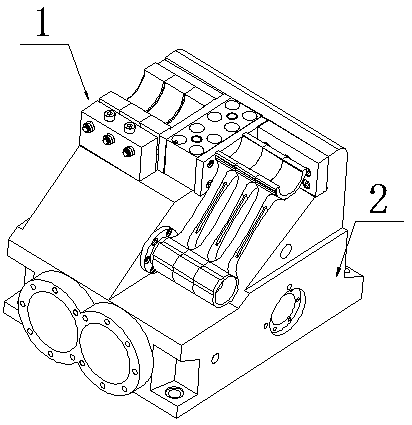
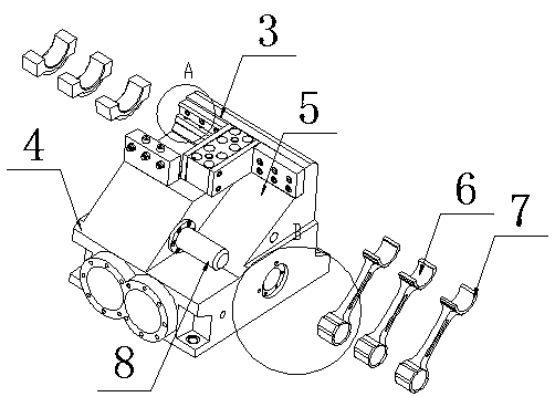
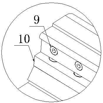
[0021] Such as Figure 1 to Figure 6 As shown, the installation and placement device 1 for the automobile seat shaft clamping bolt includes a base 2, a mounting seat 3 is arranged above the base 2, and a motor disk 4 is fixedly connected to the bottom of the mounting seat 3. The motor disk One side of the 4 is obliquely provided with a card slot 5, the outer wall of the motor disk 4 runs through a transmission shaft 8, and three swing frames 6 are sleeved on the transmission shaft 8, and a magnetic suction groove 7 is arranged above the swing frame 6, the A plurality of rotary bolts 9 are installed inside the loading seat 3, a baffle plate 10 is ...


PUM


Abstract

The invention discloses a loading and swing conveying device for automobile seat shaft clamping bolts. The loading and swing conveying device for automobile seat shaft clamping bolts comprises a base,a loading seat is arranged on the base, the lower side of the loading seat is fixedly connected with a motor plate, and one side of the motor plate is obliquely provided with a clamping groove. A transmission shaft penetrates through the outer wall of the motor plate and is sleeved with three swing frames, the upper side of each swing frame is provided with a magnetic attraction groove, a plurality of rotary connection bolts are installed in the loading seat, and a baffle is horizontally arranged below the rotary connection bolts. The lateral wall of the base is provided with a first throughconnecting hole, a locking ring is installed in the first through connecting hole, and a through groove penetrates in the base. Clamping bolts are conveyed in a swing mode jointly through the three swing frames connected to the transmission shaft in a sleeving mode, so that the device works more efficiently on the premise of guaranteeing that the occupied area is smaller. The device is convenientto operate, has good social benefits and economical benefits, and is suitable for popularization and use.

Description

technical field [0001] The invention relates to a device for loading and unloading, more precisely, a device for loading and unloading for the clamping bolt of an automobile seat shaft. Background technique [0002] The existing installation and swinging device for the car seat shaft clamping bolt has a fixed device position and cannot adjust the inclination angle of the device. The working efficiency is low, the quality is poor, the device occupies a large area, most of the parts of the mounting base are welded, the installation or disassembly of the mounting base is not convenient and fast enough, the clamping pin is easy to fall off when installing and placing the clamp, and the installation is not firm enough Shortcomings. Contents of the invention [0003] The present invention mainly solves the technical problems existing in the prior art, thereby providing a device for loading, placing, and placing the axle clamps of automobile seats. [0004] Above-mentioned tech...

Claims


Application Information

Patent Timeline
Patent Type & Authority Applications(China)
IPC IPC(8): B23Q7/00B23Q3/00
CPCB23Q3/00B23Q7/00
Inventor 李广连
Owner 抚州中垣实业有限公司
Why Eureka
Try Eureka