Rearview mirror mounting device

A technology for mounting devices and rearview mirrors, applied in optical observation devices, transportation and packaging, vehicle parts, etc., can solve problems such as difficulty in restraint and reduced rectification effect of protrusions, and achieve the goal of improving aerodynamic performance and improving aerodynamic performance Effect

Active Publication Date: 2018-03-23
HONDA MOTOR CO LTD
View PDF10 Cites 0 Cited by
  • Summary
  • Abstract
  • Description
  • Claims
  • Application Information

AI Technical Summary

Problems solved by technology

[0005] However, in the configuration of Patent Document 1, since the protrusion is arranged on the side of the mirror base (vehicle side), the distance between the mirror housing and the mirror base on the side of the vehicle is far away. In this case, the rectification effect due to the protruding part is reduced, and thus the traveling wind may be difficult to flow between the inner side wall of the mirror housing and the side of the vehicle.
For example, the running wind settled between the inner side wall of the mirror housing and the side surface of the vehicle flows into the outer side of the mirror housing (the front corner side), thereby flowing toward the outer side of the mirror housing. The amount of traveling wind (air) increases, and it may be difficult to suppress the flow of the traveling wind that has been peeled off at the front corner of the mirror housing and is drawn into the rear of the mirror housing.

Method used


Image

  • Rearview mirror mounting device
  • Rearview mirror mounting device
  • Rearview mirror mounting device

Examples


Embodiment Construction

[0025] Hereinafter, an exemplary embodiment of the present invention will be described in detail. However, the components described in this embodiment are merely examples, and the technical scope of the present invention is defined by the claims, and is not limited by the following individual embodiments.

[0026] (Configuration of rearview mirror mounting device)

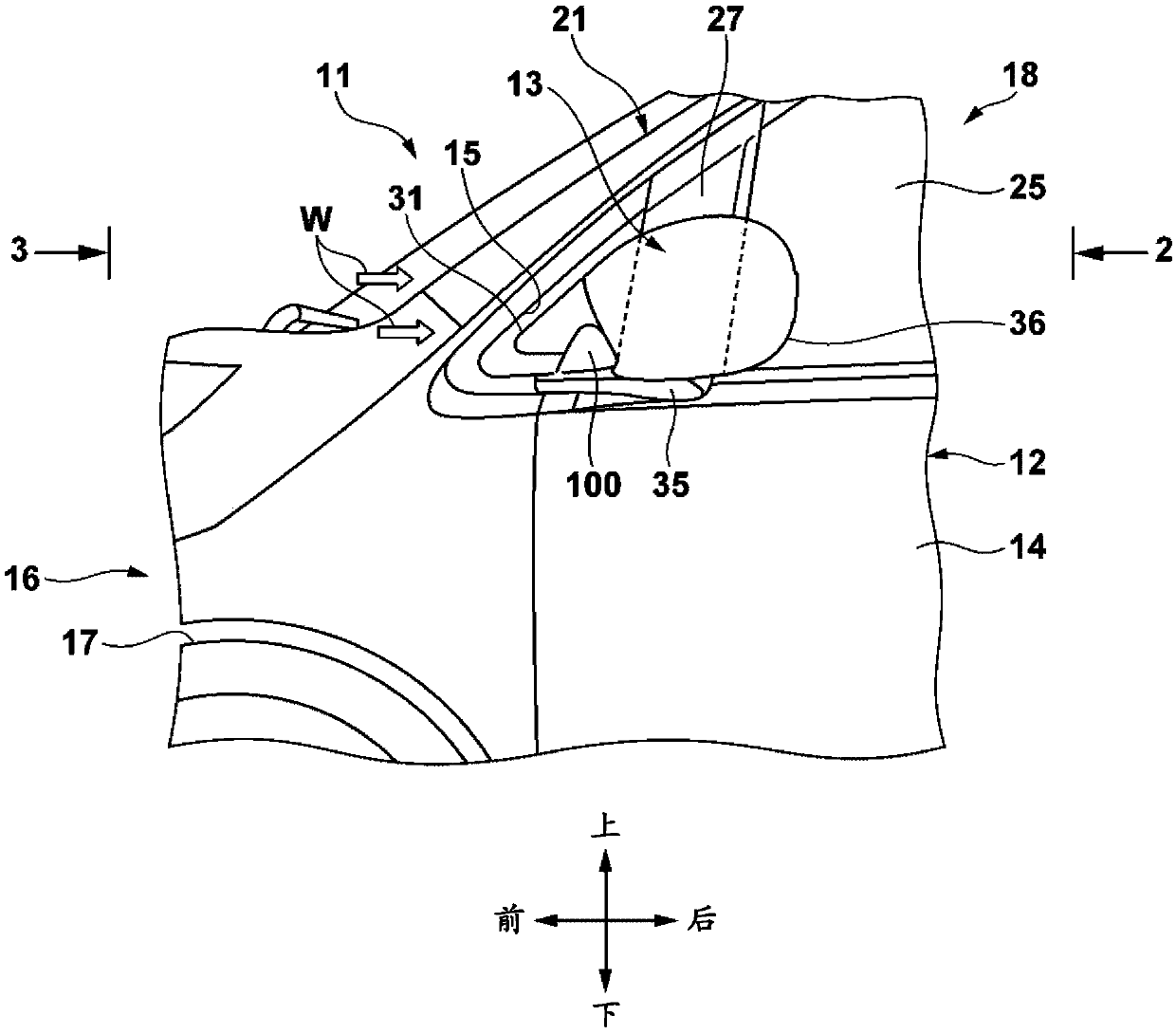
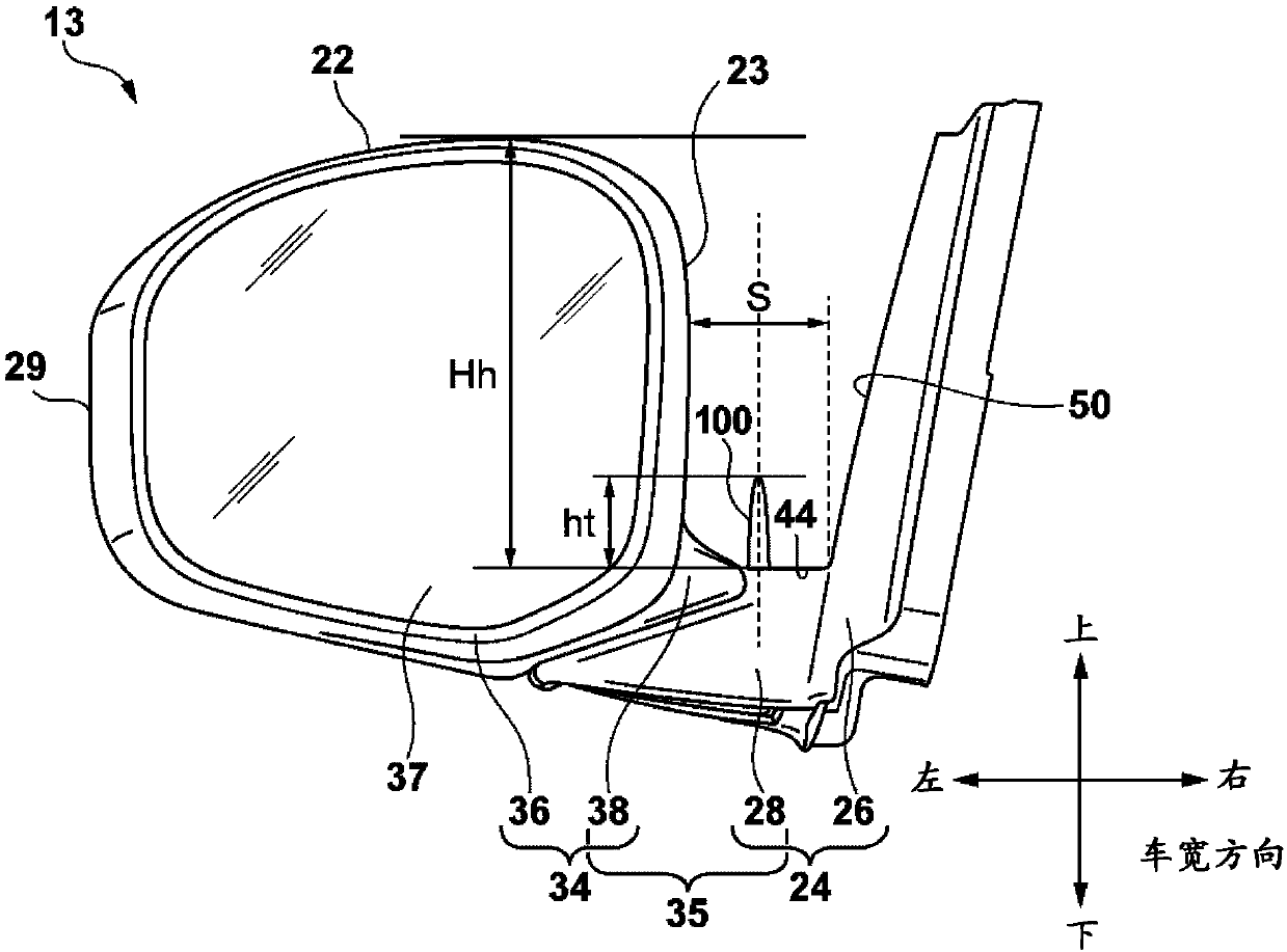
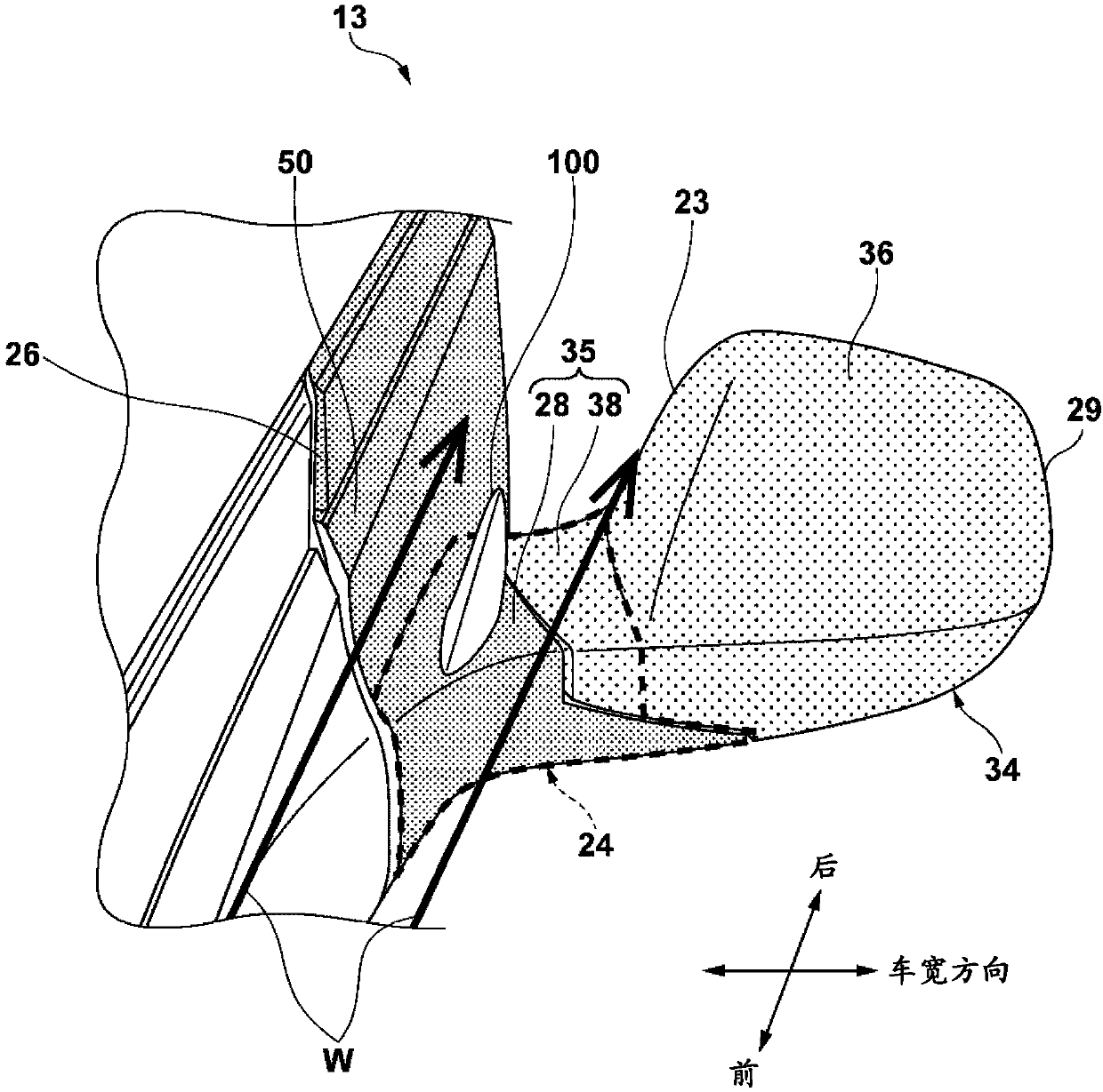
[0027] The rearview mirror attachment device of the present embodiment includes a case portion having a mirror body therein, and a connecting portion extending from the side surface of the vehicle toward the outside in the vehicle width direction and connecting the case portion and the side surface of the vehicle. The connecting portion is provided with a protruding portion which protrudes upward from the connecting portion between the side surface of the vehicle and the housing portion, and is formed such that the protruding portion is in the front-rear direction of the vehicle compared to the width direction of t...


PUM


Abstract

The invention provides a rearview mirror mounting device capable of obtaining the rectification effect even when the distance between the side surface of the vehicle and the rearview mirror housing isfar away. The rearview mirror mounting device comprises a housing portion provided with a mirror body inside, a connecting portion extending from the side surface of the vehicle toward the outside inthe vehicle width direction, and connecting the housing portion with a side surface of the vehicle; and a protruding portion which protrudes upward from the connecting portion between the side surface of the vehicle and the housing portion, and is formed to have a longer length in the front-rear direction of the vehicle than the width direction of the vehicle.

Description

technical field [0001] The present invention relates to a rearview mirror mounting device for visually confirming the rear of a vehicle. Background technique [0002] Patent Document 1 discloses a rearview mirror mounting device including: a mirror housing to which the mirror is attached; and a mirror base that holds the mirror housing on the side of the vehicle via a support arm portion . In this rear-view mirror mounting device, a protrusion extending from the side (vehicle side) of the mirror base to the side (horizontal direction) in the vehicle width direction is arranged, and is configured to be able to be attached to the rear-view mirror housing. The driving wind flowing between the mirror base and the mirror base is rectified. [0003] prior art literature [0004] Patent Document 1: Japanese Patent No. 5607181 [0005] However, in the configuration of Patent Document 1, since the protrusions are arranged on the side surface (side surface of the vehicle) of the m...

Claims


Application Information

Patent Timeline
IPC IPC(8): B60R1/06
CPCB60R1/06
Inventor 冈部浩司吉井雄一
Owner HONDA MOTOR CO LTD
Why Eureka
Try Eureka