Vacuum cleaner

A vacuum cleaner and ventilator technology, applied in the direction of vacuum cleaners, suction filters, suction nozzles, etc., can solve the problems of high-pressure head loss of connecting pipes, unfavorable aerodynamic performance of vacuum cleaners, etc., and achieve the effect of improving aerodynamic performance and reducing pressure head loss

Pending Publication Date: 2020-08-28
SEB SA
View PDF12 Cites 0 Cited by
  • Summary
  • Abstract
  • Description
  • Claims
  • Application Information

AI Technical Summary

Problems solved by technology

[0004] This arrangement of the vacuum cleaner creates a lot of turbulence in the connecting pipe when the air flow generated by the electric fan flows in the conne

Method used


Image

  • Vacuum cleaner
  • Vacuum cleaner
  • Vacuum cleaner

Examples


Example Embodiment

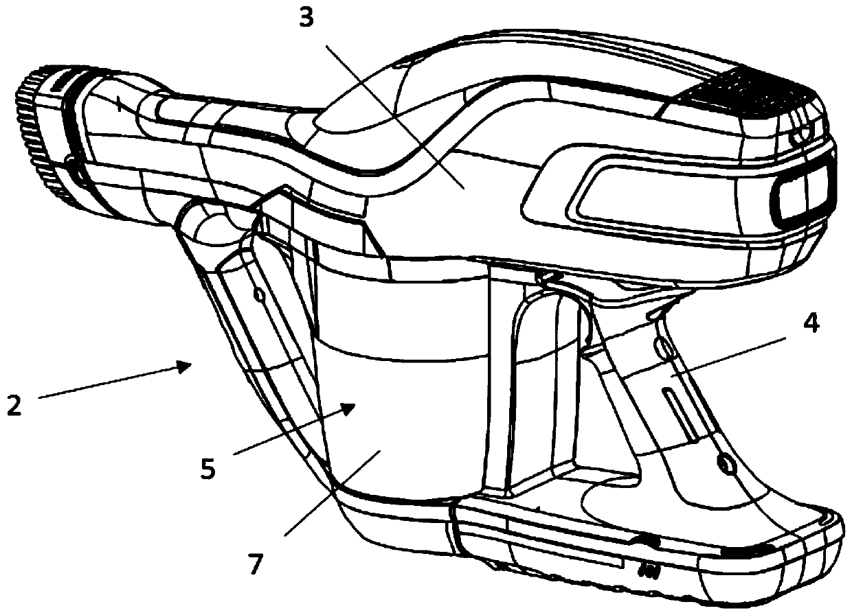
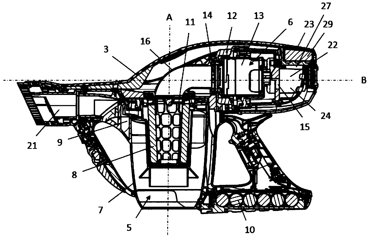
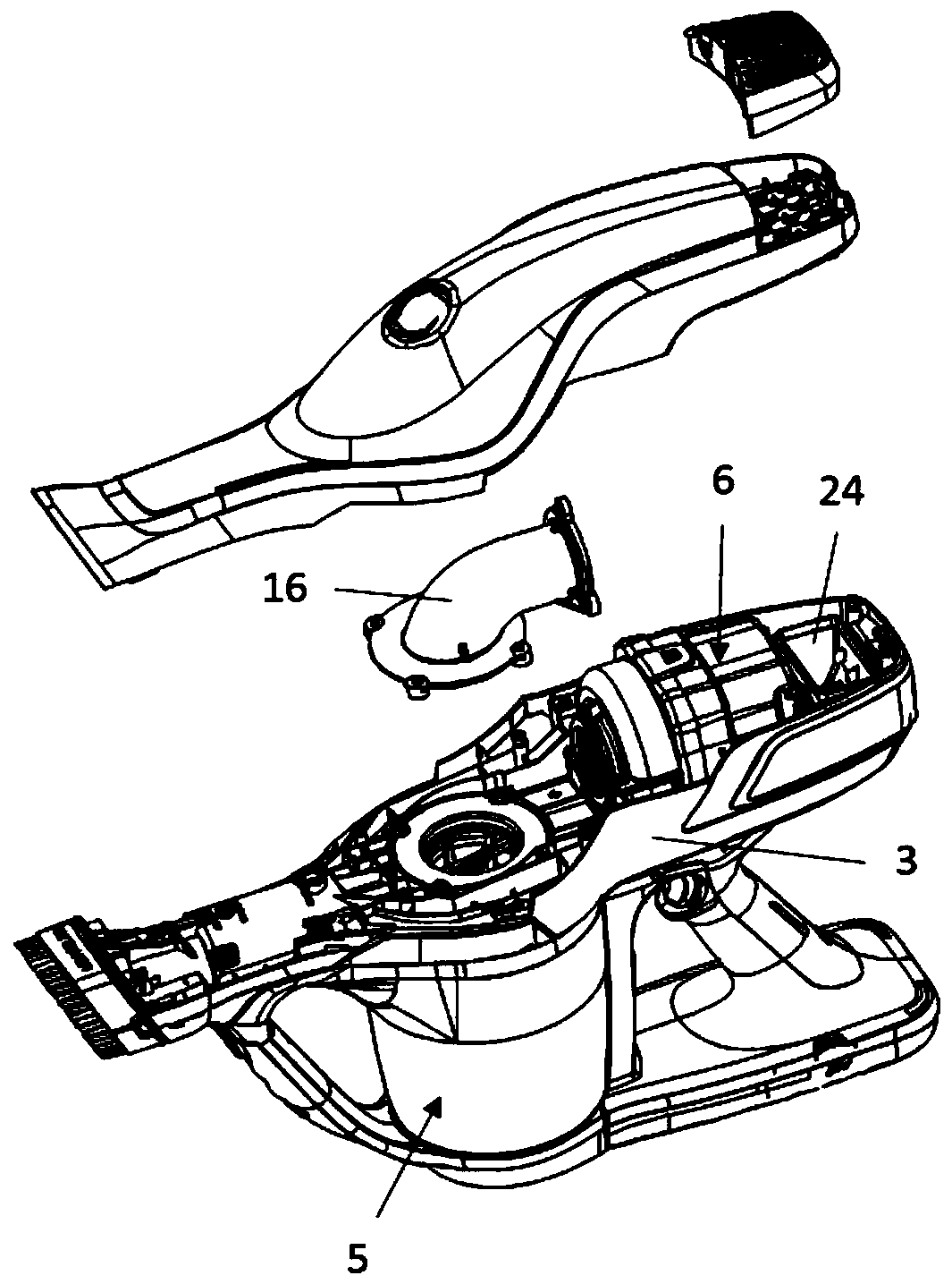
[0053] Figure 1 to Figure 7 Shown is a vacuum cleaner 2, and more particularly a portable vacuum cleaner, comprising: a main body 3 equipped with a grip handle 4, a waste separation device 5 removably mounted on the main body 3, and a body 3 accommodated in the main body 3 Inhalation device 6 in .

[0054] The waste separation device 5 is advantageously of the cyclone type and comprises in particular a waste storage container 7 and a separation filter 8 housed in the waste storage container 7 . The waste storage container 7 more specifically comprises an air inlet opening 9 and an air outlet hole 11 .

[0055] like Image 6 As shown, the suction device 6 comprises a motor housing 12 and an electric ventilator 13 arranged in the motor housing 12, which is also referred to as a suction motor. In a known manner, the motor-driven ventilator 13 comprises a ventilator and an electric motor which causes the ventilator to be driven in rotation.

[0056] according to Figure 1 to...


PUM


Abstract

A vacuum cleaner comprises: a waste separation device (5), wherein the waste separation device (5) includes an air outlet hole (11); a suction device (6), wherein the suction device (6) includes an air inlet hole (14) and an electric ventilator (13); and a connecting pipe (16), wherein the connecting pipe (16) fluidly connects the air inlet hole (14) of the suction device (6) to an air outlet hole(11) of the waste separation device (5), the electric ventilator (13) is configured to generate air flow through the air outlet hole (11), the connecting pipe (16) and the air inlet hole (14) . The connecting pipe (16) is curved and continuously extends from the air outlet hole (11) of the waste separation device (5) to the air inlet hole (14) of the suction device (6).

Description

technical field [0001] The present invention relates to the field of vacuum cleaners that allow the suction of dust and small-sized wastes present on surfaces to be cleaned, such as tile floors, floors, laminates, carpets or carpets. Background technique [0002] A vacuum cleaner, more particularly a portable vacuum cleaner, comprises in a known manner: a waste separation device comprising an air outlet hole; a suction device comprising an air inlet hole and an electric ventilator; and a connecting pipe, the connection pipe The air inlet port of the suction device is fluidly connected to the air outlet port of the waste separation device. The electric ventilator is more specifically configured to generate air flow through the air outlet holes, the connecting pipes and the air inlet holes. [0003] In such vacuum cleaners, the waste separation device generally extends substantially perpendicular to the extension axis of the electric fan, and the end of the connecting pipe or...

Claims


Application Information

Patent Timeline
IPC IPC(8): A47L5/24A47L9/00A47L9/02A47L9/10A47L9/16A47L9/24
CPCA47L5/24A47L9/16A47L9/10A47L9/02A47L9/00A47L9/248A47L9/1666A47L9/2884A47L9/0081
Inventor 伯特兰·埃斯卡莱特
Owner SEB SA
Why Eureka
Try Eureka