Fluid distributor

A fluid distributor and fluid technology, which is applied to heat exchanger shells, lighting and heating equipment, heat exchange equipment, etc., can solve the problems of low heat exchange efficiency of heat exchangers, uneven distribution of distributors, etc., and improve heat exchange efficiency , Smooth flow and low resistance

Inactive Publication Date: 2015-07-08
陆群英
View PDF10 Cites 0 Cited by
  • Summary
  • Abstract
  • Description
  • Claims
  • Application Information

AI Technical Summary

Problems solved by technology

[0004] For this reason, the technical problem to be solved by the present invention lies in the fact that the existing distributors used for heat exchangers are unevenly divided, which leads to the problem of low heat exchange efficiency of the heat exchangers, and then provide a method that can distribute the gas-liquid two-phase flow more evenly. Fluid distributor with uniformity, low pressure loss and high heat transfer efficiency

Method used


Image

  • Fluid distributor
  • Fluid distributor
  • Fluid distributor

Examples


Embodiment 1

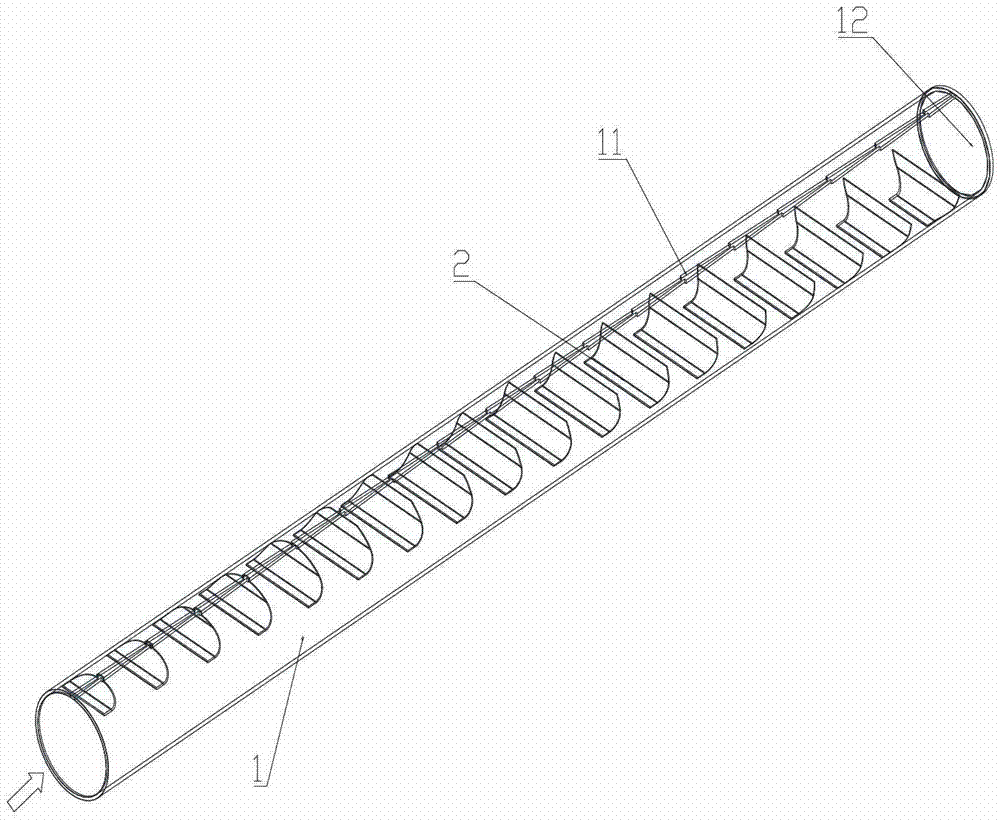
[0031] like figure 1 Shown is a fluid distributor disclosed by the present invention, which is arranged in the main fluid pipe, and is used to distribute the incoming fluid more evenly into the branch pipes.

[0032] The fluid distributor includes a distribution pipe body 1 adapted to the shape of the fluid main pipe, a distribution groove 11 is formed on the pipe wall of the distribution pipe body 1, and a sealing plate 12 is provided at the end of the distribution pipe body 1; The deflector 2 inside the pipe body 1, the deflector 2 is formed by connecting the inflow plate 21 and the outflow plate 22 with a transition arc plate in the middle, and the surface of the inflow plate 21 is along the distribution pipe body 1 The direction of the inlet of the outlet plate 21 extends along the direction of the distribution groove 11; the deflectors 2 are arranged in sequence along the length direction of the distribution pipe body 1, and the inflow plate 21 is Stepwise arrangement an...

Embodiment 2

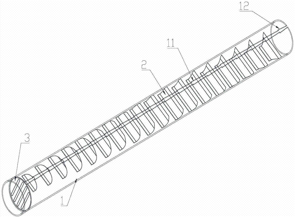
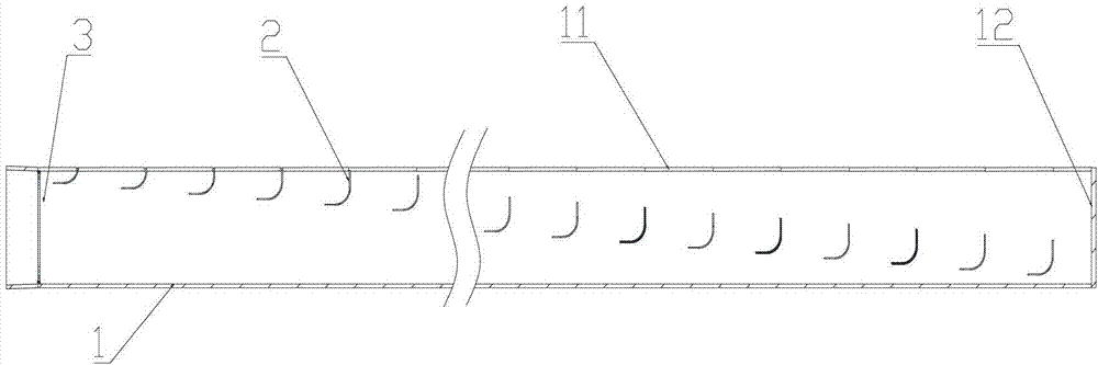
[0038] The structure of the fluid distribution pipe of this embodiment is roughly the same as that of the fluid distribution pipe of Embodiment 1, the difference lies in: in this embodiment, as figure 2 , image 3 As shown, the inlet side of the distribution pipe body 1 is provided with a flow equalizer 3 along the cross-sectional direction of the distribution pipe body 1 . Several equalizing grooves 31 are formed on the said equalizing plate 3, such as Figure 4 As shown, the widths of the equalizing grooves 31 are equal. The difference in length is less than 25%.

[0039]The length direction of the flow equalizing groove 31 is perpendicular to the direction of the plate surface of the inflow plate 21 , and the fluid is uniformly distributed on the inflow plate 21 after passing through the flow equalizing groove 31 .

[0040] In other implementations, such as Figure 5 As shown, the deflector 2 is formed with several partitions 23 along the fluid inflow direction, and th...

other Embodiment approach

[0041] In other embodiments, the angle between the inflow plate 21 and the outflow plate 22 is any angle between 80-120 degrees, which can realize the effect of equalizing the flow of the distribution pipe.

[0042] In addition, in other embodiments, the distribution groove 11 may also be a helical line along the length direction of the distribution pipe body.


PUM


Abstract

The invention discloses a fluid distributor and belongs to the fluid distributing technical field. The fluid distributor comprises a distributing pipe body and guide plates. A flow distributing groove is formed in the pipe wall of the distributing pipe body. A blanking plate is arranged at the tail end of the distributing pipe body. The guide plates are arranged in the distributing pipe body. The guide plates are connected by inlet plates and outlet plates. The plate surfaces of the inlet plates extend along the entrance direction of the distributing pipe body. The plate surfaces of the outlet plates extend along the direction of the flow distributing groove. The guide plates are sequentially ranked along the length direction of the distributing pipe body. The inlet plates are ranked of a step shape, and projected areas on a cross section of space areas of the adjacent inlet plates are basically identical. Distance from the inlet plates to the flow distributing groove increases by degrees along the entrance of the distributing pipe body to the tail end of the distributing pipe body. The fluid distributor solves the technical problems of an existing distributor that heat exchange efficiency of a heat exchanger is low due to uneven flow distributing of an existing distributor, and is particularly suitable for refrigerant distributing of a plate type heat exchanger.

Description

technical field [0001] The invention relates to a fluid distributor applied to fluid heat exchange. Background technique [0002] Generally speaking, a heat exchanger is composed of several heat exchange branches, and the fluid is usually divided into each branch through the main pipe. At present, the fluid flow direction of the fluid distributor on the market is in line with the fluid flow direction of each branch heat exchange unit. At right angles, relying on pressure difference and turbulent flow to distribute to each heat exchange unit, due to the inertia of the fluid, the flowing fluid forms an uneven pressure at each outlet of the fluid distributor, resulting in uneven fluid flow in each branch, and some branches Excessive supply of fluid and insufficient fluid supply in some branches will reduce the heat exchange efficiency of the heat exchanger and the efficiency of the entire system. Therefore, it is urgent for those skilled in the art to distribute the fluid evenl...

Claims


Application Information

Patent Timeline
Patent Type & Authority Patents(China)
IPC IPC(8): F28F9/22F28F27/02
Inventor 陆群英
Owner 陆群英
Why Eureka
Try Eureka