
Condenser condensed water sampling device separator for water and vapor

A gas-water separator and sampling device technology, which is applied in sampling device, preparation of test samples, steam generation, etc., can solve problems such as poor adaptability, poor stability and reliability, achieve good reliability, prevent gradual climb, and structure simple effect

Inactive Publication Date: 2010-08-25
JILIN GRANDPOWER EQUIP
View PDF0 Cites 0 Cited by
  • Summary
  • Abstract
  • Description
  • Claims
  • Application Information

AI Technical Summary

Problems solved by technology

This is the root cause of poor adaptability, stability and reliability of this type of sampling device.

Method used


Image

  • Condenser condensed water sampling device separator for water and vapor
  • Condenser condensed water sampling device separator for water and vapor
  • Condenser condensed water sampling device separator for water and vapor

Examples


Embodiment 1

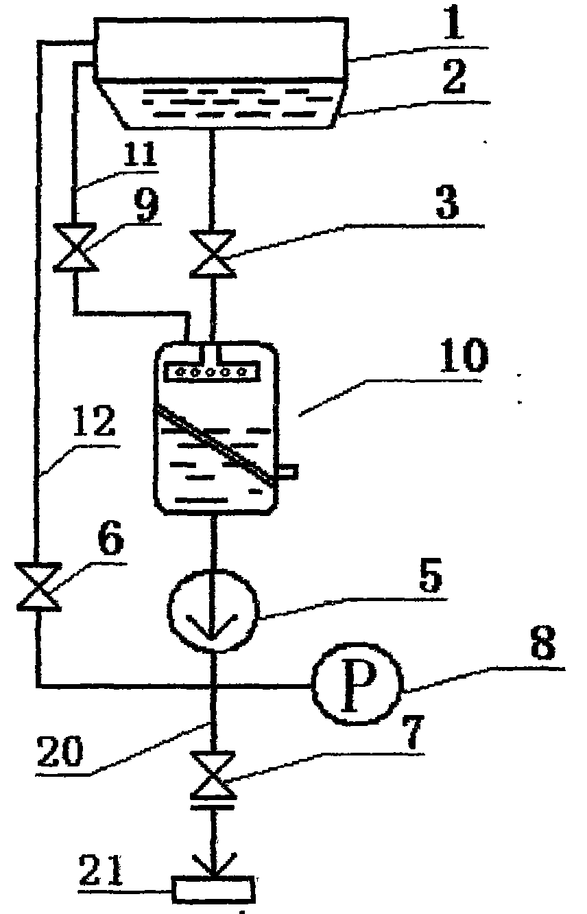
[0038] Embodiment 1: with reference to Fig. 4, the structure of the gas-water separator 10 of the condenser condensed water sampling device of embodiment 1 is, has tank body 13, is provided with sample water distributor 14 in tank body 13, in tank body 13 An air outlet 15 is provided at the upper end, and a sample water outlet 17 is provided at the lower end of the tank body 13 . Described sample water distributor 14 is a horizontal straight pipe 22, and the end of horizontal straight pipe 22 is closed, and the side wall of horizontal straight pipe 22 is provided with some water outlet holes 16, and this sample water distributor 14 from tank body 13 side walls Put it into the tank body 13 and be fixed on the side wall of the tank body 13 .

Embodiment 2

[0039] Embodiment 2: With reference to Fig. 5, the structure of the gas-water separator 10 of the condenser condensate sampling device of embodiment 2 is basically the same as that of embodiment 1, and the only difference is that the sample water distributor 14 is formed by vertically fixed connection. It is composed of two straight pipes in one body. The vertical straight pipe 23 is placed and fixedly connected to the upper end cover of the tank body 13. The two ends of the horizontal straight pipe 22 are open or closed. hole 16.

Embodiment 3

[0040] Embodiment 3: With reference to Fig. 6, the structure of the gas-water separator 10 of the condenser condensate sampling device of embodiment 3 is basically the same as embodiment 1, and the only difference is that the sample water distributor 14 is an elbow 24 and The cone shower head 25 is fixedly connected to form a whole, and an elbow 25 is placed and fixedly connected on the side wall of the tank body 13 , and a plurality of water outlet holes 16 are arranged at the lower end of the cone shower head 25 .


PUM


Abstract

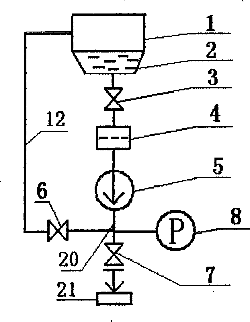
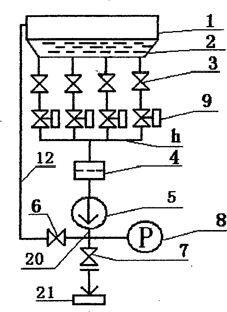
The invention relates to a gas-water separator of a condenser condensate sampling device, which is characterized by having the structure that the gas-water separator is provided with a tank body, an air outlet and a sampling water outlet are arranged on the tank body, a sampling water distributor is arranged in the tank body, the water inlet of the sampling water distributor and the sampling water outlet of the tank body are serially connected with a sampling tube at the inlet of a sampling pump, and the air outlet of the tank body is communicated with a gas-phase cavity which is arranged on the upper part of the condenser by a vacuum valve arranged on a return pipe. In the tank body, a filter screen is arranged below the sampling water distributor, and at the position of the filter screen, the side wall of the tank body is provided with a decontamination window. The gas-water separator of the condenser condensate sampling device can remove the gas precipitated by the sampling water in the sampling tube before the inlet of the sampling pump and leads the gas to return to the condenser in time, reduce the head loss of the sampling tube before the inlet of the sampling pump, preventthe occurrence of gas accumulation effect, stabilize the pressure of the sampling pump inlet and avoid the cavitation phenomena of the pump. The gas-water separator of the condenser condensate sampling device has the advantages of adaptability, stability, good reliability, long service life and simple structure, etc.

Description

technical field [0001] The invention relates to a gas-water separation device, which is a gas-water separator for a condenser condensate sampling device in thermal equipment such as a thermal power plant or a nuclear power plant. Background technique [0002] During the power generation process of a thermal power plant or a nuclear power plant, the high-temperature and high-pressure steam is cooled into condensed water in the condenser after the turbo-generator has done work, and then flows into the hot well of the condenser, and then is pumped by the condensed water pump to send Purified by the fine treatment device, the purified water or untreated feed water is reused as part of the boiler feed water. The condenser is an important part in the thermal equipment circulation system. When the heat exchange tube in the condenser wears and leaks, the industrial cooling water enters the condensed water and causes serious pollution of the condensed water. The polluted condensed wa...

Claims


Application Information

Patent Timeline
Patent Type & Authority Patents(China)
IPC IPC(8): G01N1/22G01N1/28F22D1/32
Inventor 承慰才承海东承学东王占信柴颖
Owner JILIN GRANDPOWER EQUIP
Learn More