Urea plant and method for cleaning associated gas stream

A urea device and gas flow technology, applied in the field of gas flow systems, can solve problems such as poor distribution of gas flow, difficulty in controlling formation, and reduced efficiency, and achieve the effects of low head loss, small size, and improved efficiency

Active Publication Date: 2019-11-12
SAIPEM SPA
View PDF4 Cites 0 Cited by
  • Summary
  • Abstract
  • Description
  • Claims
  • Application Information

AI Technical Summary

Problems solved by technology

[0015] Finally, especially in the latest generation of 3 / h) the distribution of the gas stream in the scrubber is poor, with the result that the efficiency is reduced; in particular, removal in the scrubber is due to the formation of aerosols that leak from the usual Gaseous ammonia is less efficient; moreover, aerosol formation is strongly pH-dependent and difficult to control

Method used


Image

  • Urea plant and method for cleaning associated gas stream
  • Urea plant and method for cleaning associated gas stream

Examples


Embodiment Construction

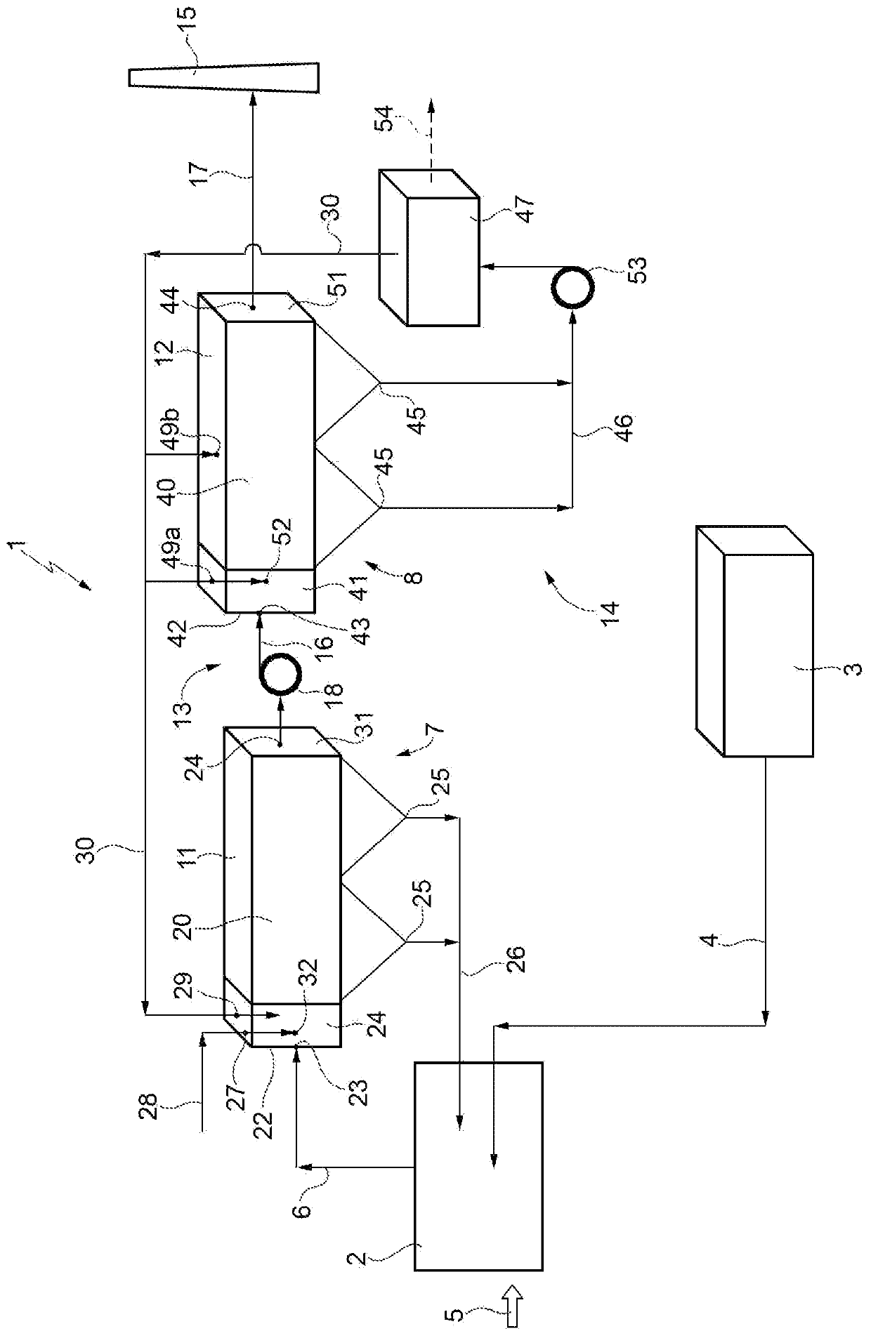
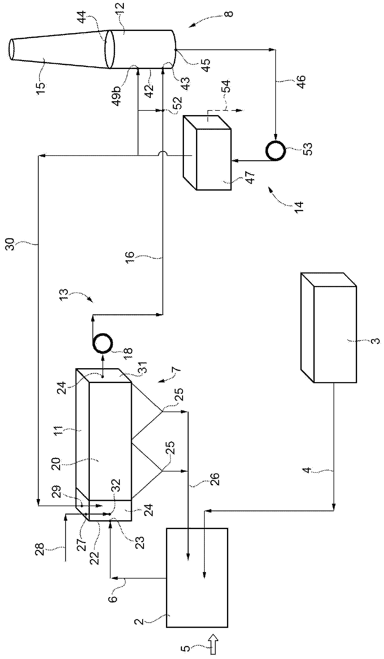
[0034] figure 1 A cleaning system 1 is schematically shown for treating a gas stream leaving a coagulation unit 2 of a urea plant 3 , in particular for removing urea powder and gaseous ammonia from said gas stream.

[0035] The urea plant 3 is basically known per se and will therefore not be described or illustrated in detail. In general, the urea plant 3 comprises: a urea synthesis reactor, in which the urea synthesis reaction from ammonia and carbon dioxide takes place; The resulting urea solution is gradually concentrated, removing water and unreacted ammonia and carbon dioxide, and recirculating the recovered components; and a vacuum section, which is equipped with a vacuum system and connected to the waste water treatment section.

[0036] The urea plant 3 is connected to the solidification unit 2 via the urea supply line 4, the solidification unit comprises, for example, a granulator or a prilling tower, and the molten urea produced in the urea plant 3 is transported to...


PUM


Abstract

A cleaning system (1) for cleaning a gas stream from a solidification unit (2) of a urea plant (3) comprises a first removal device (7) for removing urea powder and a second removal device (8) for removing ammonia, the two removal devices (7, 8) being arranged in series along a gas treatment circuit (13) and connected by a connecting line (16); at least one of the two removal devices (7, 8) is an electrostatic precipitator (11, 12) designed to remove substantially all or at least most of the contaminant treated in the removal device (7, 8), i.e. urea powder or ammonia.

Description

technical field [0001] The present invention relates to a system and method for cleaning a gas stream from a coagulation unit of a urea plant. Background technique [0002] In a typical industrial urea production plant (urea plant), urea is produced in a synthesis reactor, then gradually concentrated (up to a value of approximately 96-99.7%), and finally coagulated in a coagulation section, usually by a granulator or a prilling tower from which the final commodity in the form of urea granules or urea pellets is obtained. [0003] Typically, the urea delivered to the prilling machine or prilling tower is liquid and solidified by a stream of ambient air. [0004] When the air used for coagulation leaves the coagulation section, it contains urea powder and ammonia released by the liquid urea during cooling and coagulation. [0005] It is therefore possible to purify the air precisely by removing the urea powder and the ammonia it contains, before releasing it into the atmosph...

Claims


Application Information

Patent Timeline
Patent Type & Authority Patents(China)
IPC IPC(8): B01D53/32B03C3/013B03C3/017B03C3/02B03C3/16C07C273/16
CPCB01D53/323B01D53/54B01D53/58B01D53/79B01D2251/206B01D2251/608B01D2257/40B01D2257/406B01D2258/02B01D2259/124B03C3/013B03C3/017B03C3/025B03C3/16C07C273/16Y02A50/20
Inventor 洛伦佐·布鲁诺利诺·卡莱西
Owner SAIPEM SPA
Why Eureka
Try Eureka