Corrosion-free energy saving chimney

A chimney and flue gas technology, applied in the field of chimneys, can solve problems such as difficult construction, increased resistance to rising of flue gas, increased pressure loss, etc., and achieve convenient and simple construction operation process, increase initial speed and power, and diversion effect Reduced effect

Inactive Publication Date: 2012-06-06
ZHONGHUAN HUACHUANG BEIJING TECH DEV
View PDF4 Cites 0 Cited by
  • Summary
  • Abstract
  • Description
  • Claims
  • Application Information

AI Technical Summary

Problems solved by technology

However, in this type of flue inlet, a large part of the flue gas flow will be blown obliquely to the gas that has just come in from the inlet after the tangential air intake rotates for a circle, causing the inlet air to deflect to the wall of the cylinder and cause compression, making the wall surface The flow velocity at the place increases, and the wall friction increases, resulting in an increase in pressure loss, an increase in the rising resistance of the flue gas, and a disordered flue gas flow field. In this way, the operating cost of the chimney cannot be reduced, energy saving is not achieved, and condensation in the wet flue gas cannot be effectively solved. Corrosion caused by strong corrosive substances such as acid to the chimney lining and cylinder
[0006] In addition, in the prior art, a spiral rifling structure is set on the inner wall of the chimney, which acts to guide the rising flue gas flow, promotes the rotation of the flue gas and generates a central negative pressure, but this spiral rifling structure is formed by the suspension The blocks picked on the wall of the cylinder are stacked up and down in dislocation, such as Figure 9 As shown, the upper and lower masonry is in a stepped concave-convex shape, and the cross-section and surface of the block are rough and uneven, which has great resistance to the rising smoke, which increases the energy consumption of the induced draft fan and cannot achieve an effective diversion effect; Moreover, during the construction process, the ascending inclination angle of the helix is ​​realized by the parallel displacement and staggered joints between the upper and lower stacked blocks. It is more difficult to control the accuracy of the inclination angle of the helix required by the design drawings, and it is easy to cause the helix The deviation of the overall angle makes the construction difficult, and the construction technology is not easy to control; in order to overcome the unevenness of the steps between the masonry and the rough surface, acid-resistant cement mortar is used to smooth the unevenness, but under actual working conditions After running for a short period of time, the mortar on the surface will be washed away by the rising flue gas flow and fall off, which cannot achieve the permanent effect; in addition, the length of the blocks suspended on the inner wall of the chimney is single in the spiral rifling structure of the prior art , after the flue gas rises from the bottom to the upper part of the chimney cylinder (the small slope ratio stage in the cylinder), the diameter of the corresponding cross section decreases, but the length of the cantilever protruding from the chimney lining wall does not decrease, As a result, it cannot effectively divert the rising flue gas flow, but instead increases the resistance of the flue gas rising, which is easy to cause the desulfurization wet flue gas to wash and corrode the circular support platform that penetrates the inner lining of the cylinder and the chimney cylinder. Fundamentally Solve the Corrosion Problem of Desulfurization Wet Chimney

Method used


Image

  • Corrosion-free energy saving chimney
  • Corrosion-free energy saving chimney
  • Corrosion-free energy saving chimney

Examples


Embodiment Construction

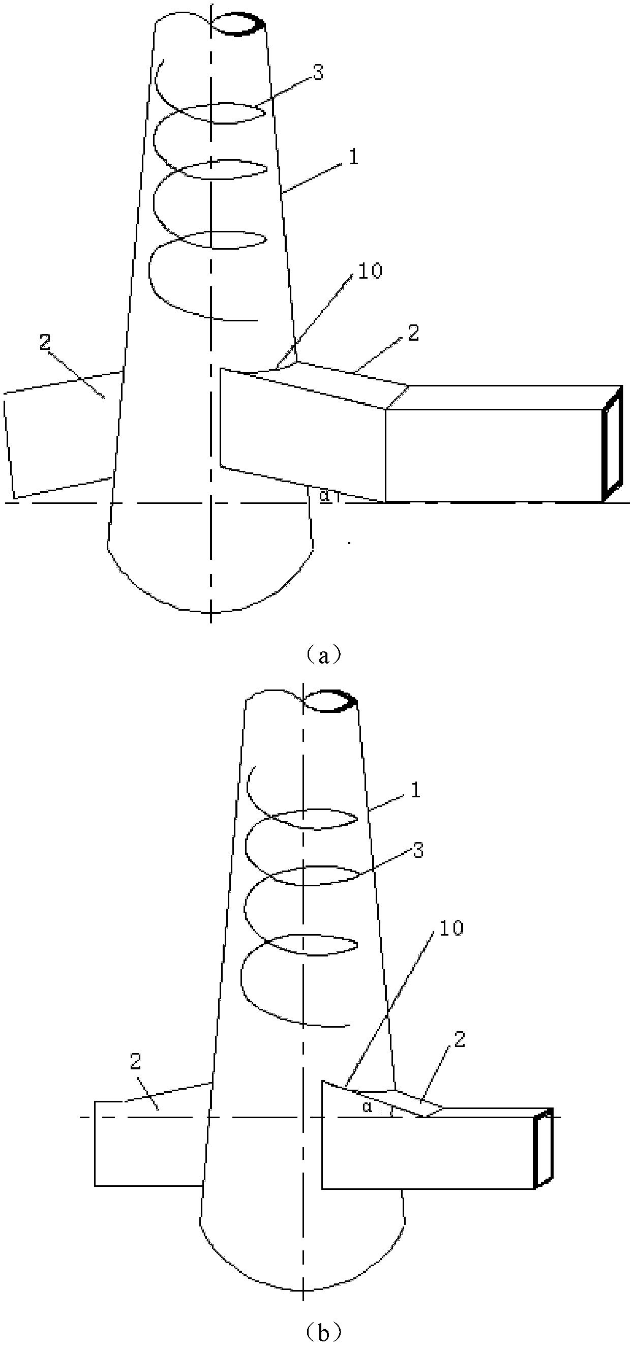
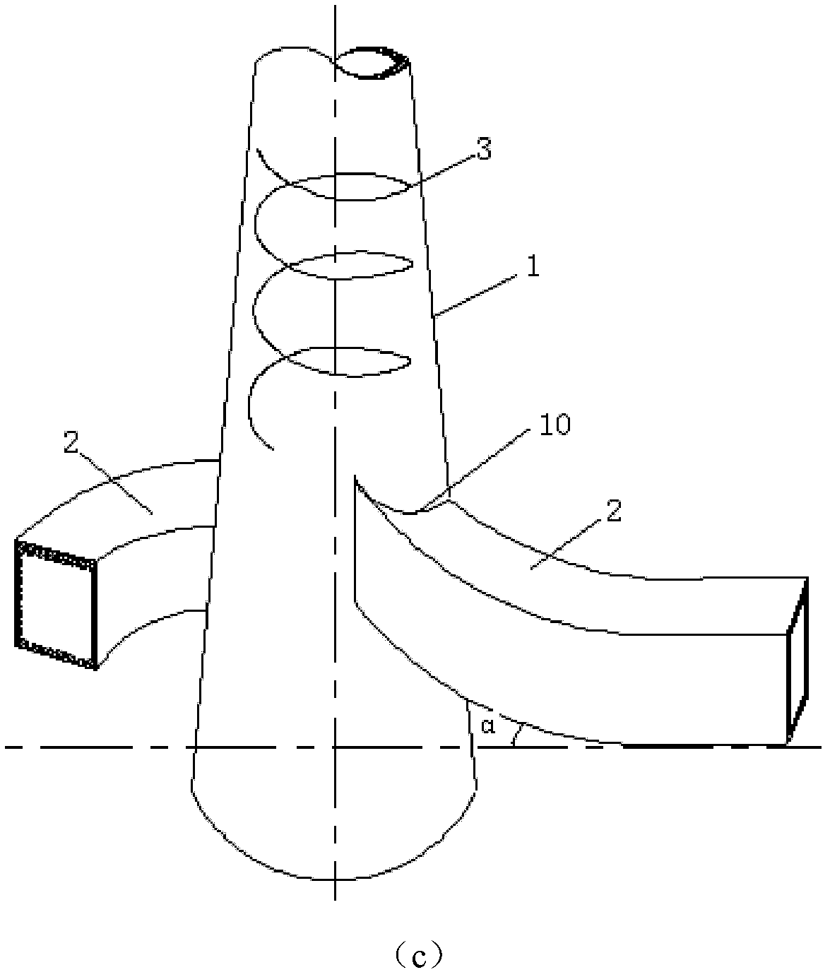
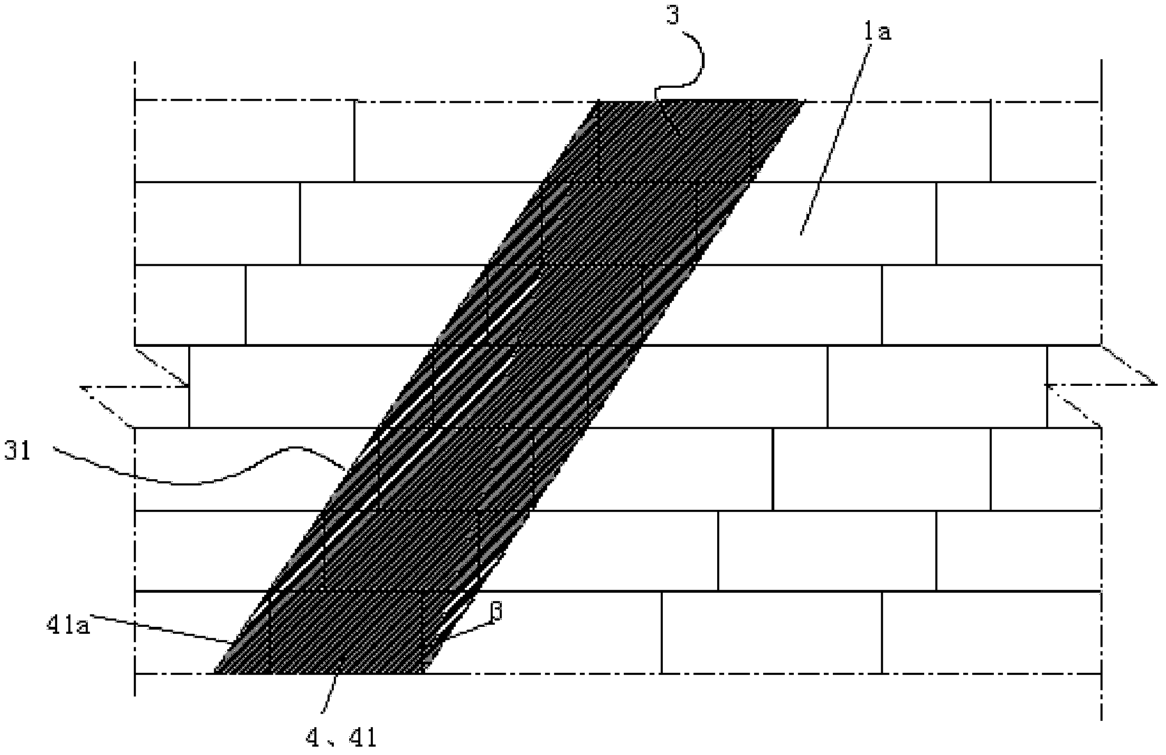
[0040] Such as figure 1As shown in the schematic diagram of the overall structure of the non-corrosion energy-saving chimney of the present invention, the non-corrosion energy-saving chimney of the present invention includes a chimney cylinder 1, a spiral flue gas guide line 3 is provided on its inner lining 1a, and a tube wall at its lower end is provided with The smoke inlet 10; the flue inlet 2, one end of which is connected to the smoke inlet 10, communicates with the inside of the chimney cylinder through the smoke inlet 10; wherein, the spiral flue gas guide line 3 has a guide part 41 in multiple pieces The blocks are stacked by 4, such as figure 2 As shown, the guide portion 41 of each block 4 has a smooth inclined surface 41a so that the inclined surfaces of all the stacked blocks are smoothly connected, thereby forming the guide surface 31 for making the smoke rise in a rotating manner.

[0041] Such as figure 2 As shown, the spiral flue gas guide line 3 of the p...


PUM


Abstract

The invention discloses a corrosion-free energy saving chimney. The chimney comprises a chimney tube (1), a flue (2) and a spiral smoke guide line (3), wherein the spiral smoke guide line (3) is arranged on a liner (1a) of the chimney tube; a smoke inlet (10) is arranged at the lower end of the chimney tube; one end of the flue is connected at the smoke inlet (10) and is communicated with the interior of the chimney tube (1) via the smoke inlet (10); the spiral smoke guide line (3) is formed by stacking a plurality of building blocks (4) with guide parts (41); and the guide part (41) of each building block (4) is provided with a smooth slope (41a), so that the slopes (41a) of all the building blocks (4) stacked together are smoothly connected, thus forming a guide surface (31) for the smoke to rise in a rotary manner. The chimney has the following beneficial effects that: the energy consumption of the draught fan can be reduced by about 20%, thus being beneficial to saving energy; meanwhile, the problem of corrosion of the inner tube and outer wall of the wet chimney after desulfurization can be thoroughly solved; and compared with the existing chimneys, the chimney has obvious energy saving and environmental protection effects and lower manufacturing cost.

Description

technical field [0001] The invention relates to a chimney, in particular to a corrosion-free and energy-saving chimney. Background technique [0002] In recent years, with the steady implementation of national environmental protection policies and the enhancement of public environmental awareness, the operation of domestic flue gas desulfurization systems in industries such as electric power, metallurgy, and chemical industry has entered normalization and standardization. Generally, smoke exhaust enterprises adopt the wet flue gas desulfurization process, which has a very high removal efficiency of SO2 in the flue gas, about 95%, but the removal efficiency of SO3, the main component of flue gas corrosion, is not high, about 20%. . The flue gas temperature after wet desulfurization is about 40°C-50°C, the flue gas is saturated, the water content is high, the humidity is high, the temperature is low, and the flue gas is in a state of condensation. The flue gas in the convent...

Claims


Application Information

Patent Timeline
Patent Type & Authority Applications(China)
IPC IPC(8): E04H12/28
Inventor 包钦丹李颖梁远忠张申楠
Owner ZHONGHUAN HUACHUANG BEIJING TECH DEV
Why Eureka
Try Eureka