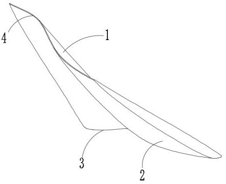
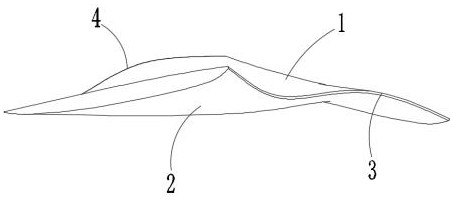
Composite bionic airfoil blade and axial flow fan impeller
A technology of bionic wings and blades, which is applied in wind power generation, mechanical equipment, machines/engines, etc., can solve problems such as difficulty in popularization and application, few attempts to improve aerodynamic performance, poor noise control and aerodynamic performance, and achieve improved airflow distribution. Layer, improve fan performance, improve the effect of aerodynamic performance
Active Publication Date: 2022-04-29
FOSHAN CITY NANHAI POPULA FAN
View PDF0 Cites 0 Cited by
- Summary
- Abstract
- Description
- Claims
- Application Information
AI Technical Summary
Problems solved by technology
[0002] The blades of traditional axial flow fan impellers are generally of sheet metal structure. The blades of sheet metal structure are easy to manufacture, but their performance in noise control and aerodynamic performance is poor.
[0003] For this reason, existing technologies improve the performance of blades and impellers by improving blade airfoil, blade inclination and sweeping direction, and optimizing blade top plate. Although certain effects have been achieved, many of these improvements are aimed at specific fans or specific It is difficult to popularize an
Method used
View moreImage
Smart ImageViewing Examples
Examples
 PUM
| Property | Measurement | Unit |
|---|---|---|
| Angle | aaaaa | aaaaa |
| Radius | aaaaa | aaaaa |
| Radius | aaaaa | aaaaa |
Abstract
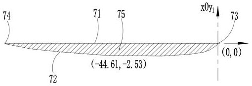
The invention relates to the technical field of fan blades, in particular to a composite bionic airfoil blade and an axial flow fan impeller. The composite bionic airfoil blade is obtained by scaling and rotating an airfoil section at equal ratio and sweeping along a space curve. The airfoil section comprises a windward line and a leeward line, the windward line is a straight line, the leeward line is a curve protruding downwards, the windward line and the leeward line intersect to form a front point and a rear point, and after sweeping, the windward line, the leeward line, the front point and the rear point are swept to form the windward side, the leeward side, the front edge and the rear edge of the composite bionic airfoil blade respectively. In the sweeping process of the airfoil section from the blade root to the blade top, the scaling condition is that scaling is conducted firstly and then scaling is conducted, the rotation direction is anticlockwise, and the sweeping track is shifted in the rear lower direction firstly and then in the front lower direction. According to the composite bionic airfoil blade, the end boundary layer can be thinned, accumulation of the corner area boundary layer close to the leeside can be removed, airflow layering of the end area is improved, and therefore the aerodynamic performance is improved, and the fan performance is improved.
Description
technical field [0001] The invention relates to the technical field of fans, in particular to a composite bionic airfoil blade and an axial flow fan impeller. Background technique [0002] The blades of traditional axial flow fan impellers are generally of sheet metal structure. The blades of sheet metal structure are easy to manufacture, but their performance in noise control and aerodynamic performance is poor. [0003] For this reason, existing technologies improve the performance of blades and impellers by improving blade airfoil, blade inclination and sweeping direction, and optimizing blade top plate. Although certain effects have been achieved, many of these improvements are aimed at specific fans or specific It is difficult to popularize and apply what is carried out according to the requirements of working conditions. [0004] In recent years, some people have tried to use bionic technology to improve the performance of blades, such as setting non-smooth leading ed...
Claims
Login to View More Application Information
Patent Timeline
 IPC IPC(8): F04D29/38F04D29/36F04D29/66
CPCF04D29/386F04D29/36F04D29/666Y02E10/72
Inventor 何乃彪霍慧林志良
Owner FOSHAN CITY NANHAI POPULA FAN
Features
- R&D
- Intellectual Property
- Life Sciences
- Materials
- Tech Scout
- Unparalleled Data Quality
- Higher Quality Content
- 60% Fewer Hallucinations
Learn More Browse by: Latest US Patents, China's latest patents, Technical Efficacy Thesaurus, Application Domain, Technology Topic, Popular Technical Reports.
© 2025 PatSnap. All rights reserved.Legal|Privacy policy|Modern Slavery Act Transparency Statement|Sitemap|About US| Contact US: help@patsnap.com


