
Car-mounted car-sickness-resisting structure

An anti-sickness and car roof technology, applied in vehicle parts, air handling equipment, life-saving equipment, etc., can solve problems such as unrealistic opening of car windows, difficulty for people with motion sickness to enjoy car benefits, and inability to prevent motion sickness. Motion sickness effect, good air handling effect, easy operation effect

Inactive Publication Date: 2018-03-23
DONGGUAN UNIV OF TECH
View PDF0 Cites 2 Cited by
  • Summary
  • Abstract
  • Description
  • Claims
  • Application Information

AI Technical Summary

Problems solved by technology

[0002] With the development of science and technology and the improvement of people's living standards, the use of cars has become more and more widespread. The widespread use of existing cars has facilitated the lives of most people, but it is still difficult for people with motion sickness to enjoy the benefits brought by cars.
[0003] Motion sickness can be divided into many aspects. There are motion sickness caused by the shaking of the vehicle, and motion sickness caused by the turbid air in the vehicle. However, maintaining a smooth air circulation is an effective way to reduce motion sickness, so opening the windows can alleviate it to a certain extent. Motion sickness phenomenon, but opening the car window has great limitations. Due to various factors, it is unrealistic to open the car window in rainy and low temperature weather, and it still cannot effectively prevent motion sickness for a long time. Therefore, it is urgent to install it on the car. An anti-motion sickness mechanism that can conduct precise air communication with the outside world at any time, so as to relieve motion sickness symptoms of motion sickness people

Method used


Image

  • Car-mounted car-sickness-resisting structure
  • Car-mounted car-sickness-resisting structure
  • Car-mounted car-sickness-resisting structure

Examples


Embodiment Construction

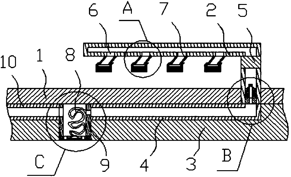
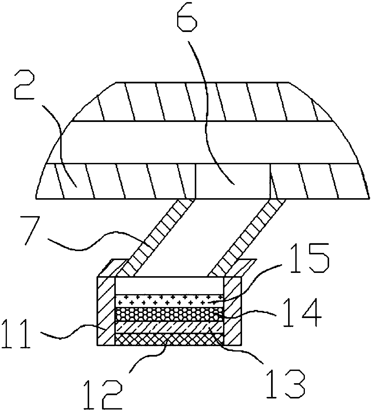
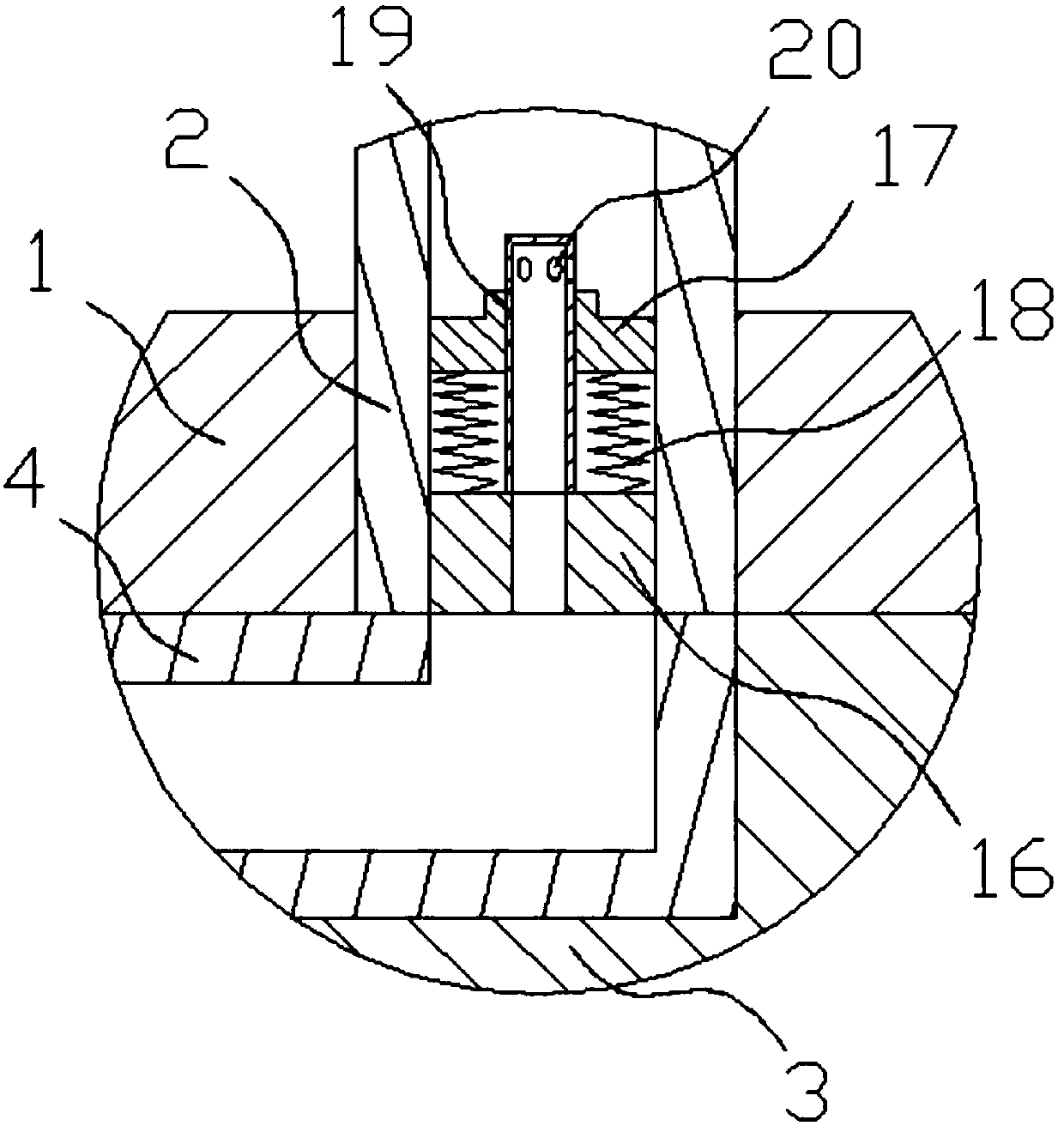
[0029] In order to enable those skilled in the art to better understand the technical solution of the present invention, the present invention will be described in detail below in conjunction with the accompanying drawings. The description in this part is only exemplary and explanatory, and should not have any limiting effect on the protection scope of the present invention. .

[0030] Such as Figure 1-Figure 6 Shown, the concrete structure of the present invention is: a kind of vehicle-mounted anti-motion sickness mechanism, and it comprises roof board 1 and the luggage rack 2 that is arranged on the roof board 1, and described luggage rack 2 is L-shaped hollow square steel, and its The lower plate of the horizontal part is uniformly provided with an air suction port 6, and the bottom of the air suction port 6 is connected with an air suction inclined pipe 7, and the bottom of the vertical part of the luggage rack 2 passes through the roof panel 1 and It communicates with t...


PUM


Abstract

The invention relates to a vehicle-mounted anti-motion sickness mechanism, which includes a roof plate and a luggage rack arranged on the roof plate. The luggage rack is an L-shaped hollow square steel, and the lower plate of the horizontal part is uniformly provided with air suction ports. The lower part of the suction port is connected with an air suction inclined pipe, the lower part of the vertical part of the luggage rack passes through the roof panel and communicates with the air inflow pipe provided on the lower surface of the roof panel, and the vertical part of the luggage rack is provided with an air suction pump. The lower surface of the top plate is also provided with a storage cylinder that cooperates with the end of the air inflow pipe, and a respirator connected with the air inflow pipe is placed in the storage cylinder, and the lower surface of the storage cylinder cooperates with an openable storage cover. A decorative soft board wrapping the air inflow pipe and the storage tube is arranged at the bottom; the present invention makes the luggage rack on the existing roof into a hollow square steel structure, and sets an air suction port and an air suction inclined pipe on the lower surface of the luggage rack , will not affect the overall structure and appearance of the car, and can eliminate the interference of external factors to achieve a good anti-motion sickness effect.

Description

technical field [0001] The invention relates to the field of automobile equipment structures, in particular to a vehicle-mounted anti-motion sickness mechanism. Background technique [0002] With the development of science and technology and the improvement of people's living standards, the use of cars is becoming more and more extensive. The widespread popularization of existing cars has facilitated the lives of most people, but it is still difficult for people with motion sickness to enjoy the benefits brought by cars. [0003] Motion sickness can be divided into many aspects. There are motion sickness caused by the shaking of the vehicle, and motion sickness caused by the turbid air in the vehicle. However, maintaining a smooth air circulation is an effective way to reduce motion sickness, so opening the windows can alleviate it to a certain extent. Motion sickness phenomenon, but opening the car window has great limitations. Due to various factors, it is unrealistic to o...

Claims


Application Information

Patent Timeline
IPC IPC(8): B60R5/00B60H3/06A62B7/12A62B23/02
CPCB60R5/003A62B7/12A62B23/02B60H3/0608B60H2003/0691
Inventor 白云李川
Owner DONGGUAN UNIV OF TECH
Learn More