
Water draining structure for draining water on two sides of tunnel

A drainage structure and tunnel technology, applied in drainage, safety devices, mining equipment, etc., can solve the problem of inability to achieve fast and efficient drainage, and achieve the effect of increasing drainage capacity, increasing drainage speed, and simple drainage structure.

Pending Publication Date: 2018-03-23
海宁善能制冷科技有限公司
View PDF11 Cites 0 Cited by
  • Summary
  • Abstract
  • Description
  • Claims
  • Application Information

AI Technical Summary

Problems solved by technology

With the development of science and technology, human beings have also made major breakthroughs in the development of tunnel technology, and various tunnels are also emerging one after another. Since tunnels are built underground, water accumulation in tunnels is especially common, so tunnel drainage is very important, but in the existing technology In the tunnel drainage, fast and efficient drainage cannot be achieved

Method used


Image

  • Water draining structure for draining water on two sides of tunnel
  • Water draining structure for draining water on two sides of tunnel

Examples


Embodiment Construction

[0013] The following will clearly and completely describe the technical solutions in the embodiments of the present invention with reference to the accompanying drawings in the embodiments of the present invention. Obviously, the described embodiments are only some, not all, embodiments of the present invention. Based on the embodiments of the present invention, all other embodiments obtained by persons of ordinary skill in the art without making creative efforts belong to the protection scope of the present invention.

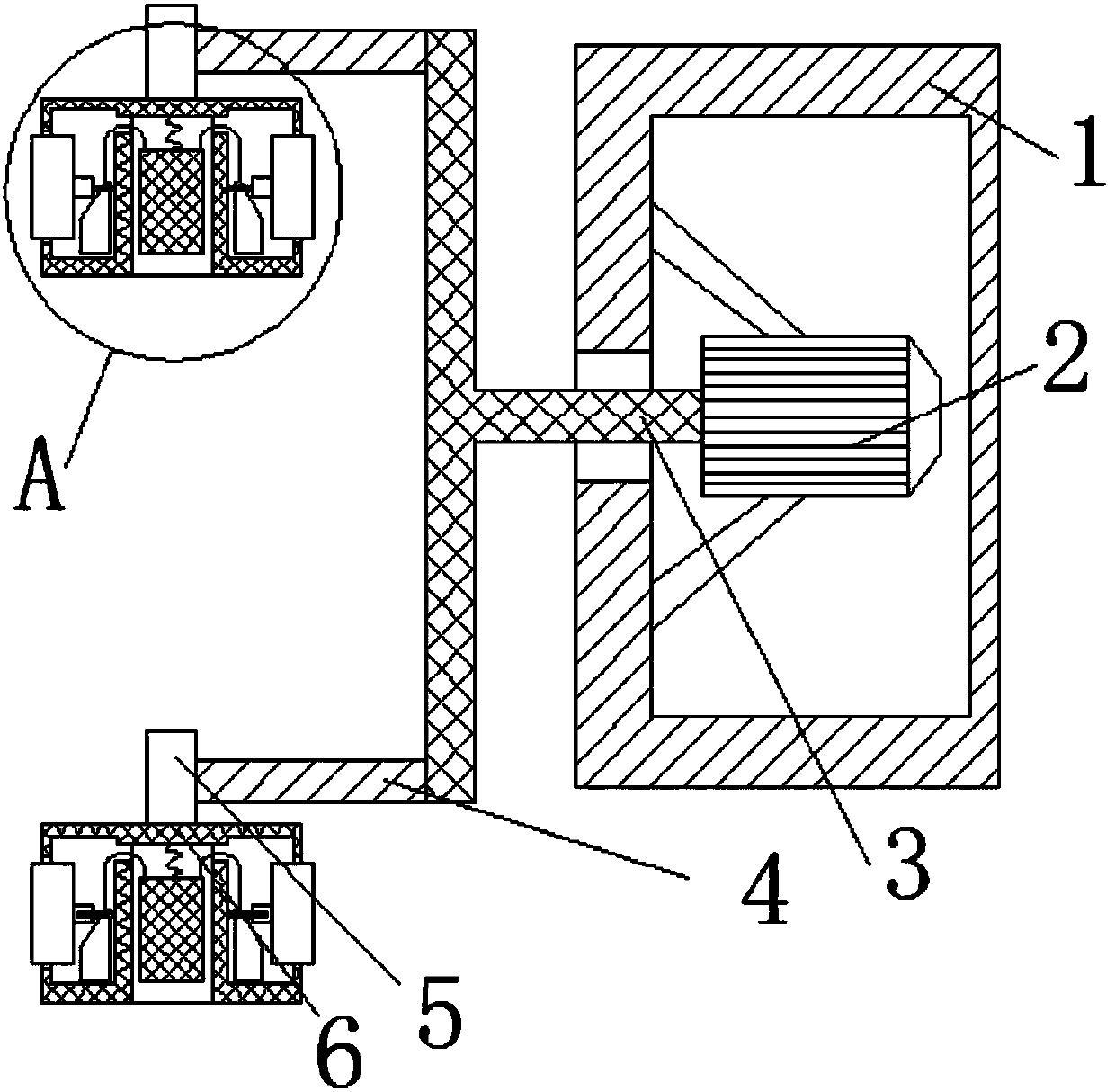
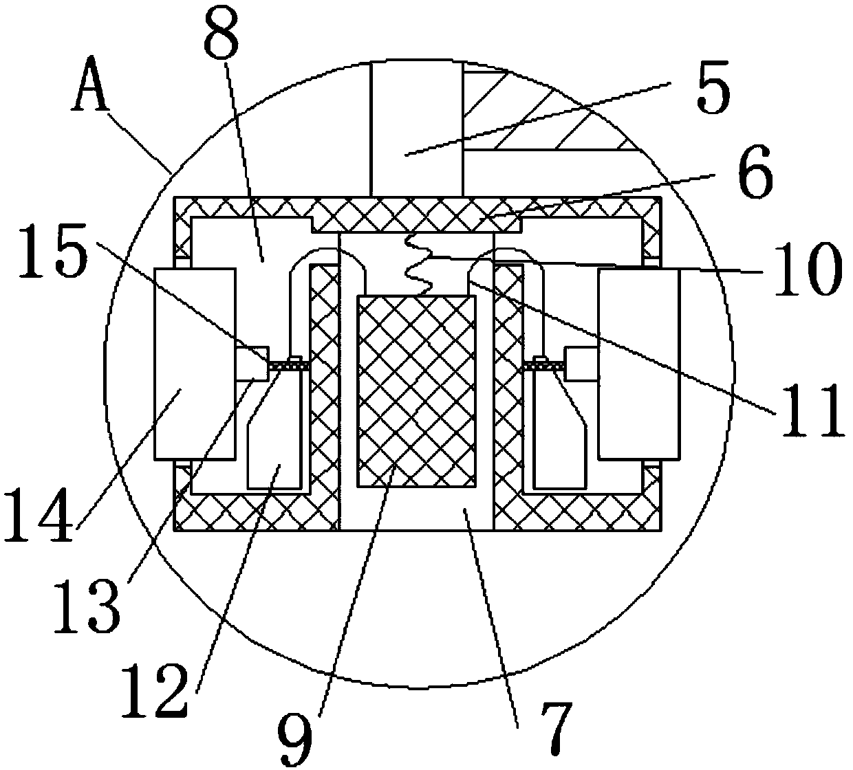
[0014] see Figure 1-2 , the present invention provides a technical solution:

[0015] A drainage structure for drainage on both sides of a tunnel, comprising a rectangular box 1 and a motor 2, the motor 2 is fixedly connected to the inner wall of the rectangular box 1 through a tripod, the outer wall of the other end of the rectangular box 1 is fixedly connected to the wall, and the motor 2 A T-shaped connecting rod 3 is connected through a coupling, and a h...


PUM


Abstract

The invention discloses a water draining structure for draining water on two sides of a tunnel. The water draining structure comprises a rectangular tank and a motor. The water draining structure fordraining the water on the two sides of the tunnel has the advantages that the water draining structure is simple, structures such as a T-shaped connecting rod, second movable plates and rubber bands are combined with one another, a power switch can be turned on, the T-shaped connecting rod can be driven by the motor to rotate, a fan plate can be driven under the rotation action of the T-shaped connecting rod to rotate, a first movable plate can move towards the outside of the fan plate under the effect of centrifugal force on the fan plate, push plates can be pulled by steel ropes under the movement action of the first movable plate to move, third connecting rods can be squeezed under the movement actions of the push plates, accordingly, the second movable plates can be pushed out of the fan plate, the area in contact with external water can be enlarged at the moment as the first movable plate and the second movable plates outwardly extend, the water draining capacity can be improved,and the water draining speeds of the water draining structure can be increased by the aid of the centrifugal force.

Description

technical field [0001] The invention relates to the technical field of tunnels, in particular to a drainage structure for drainage on both sides of a tunnel. Background technique [0002] Drainage refers to artificial control of water flow, artificial drainage, measures to remove and treat excess water. Farmland drainage is one of the important measures to improve agricultural production conditions and ensure high crop yields. With the development of science and technology, human beings have also made major breakthroughs in the development of tunnel technology, and various tunnels are also emerging one after another. Since tunnels are built underground, water accumulation in tunnels is especially common, so tunnel drainage is very important, but in the existing technology In the case of tunnel drainage, fast and efficient drainage cannot be achieved. Contents of the invention [0003] The purpose of the present invention is to provide a drainage structure for drainage on ...

Claims


Application Information

Patent Timeline
Patent Type & Authority Applications(China)
IPC IPC(8): E21F16/02
CPCE21F16/02
Inventor 方园谷俊杰樊世祥
Owner 海宁善能制冷科技有限公司
Learn More